Reducing cyclic rate: theory
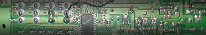
The transmitter uses 5k potentiometers for cyclic, rudder, and throttle/collective. They are connected as voltage dividers, the outputs of which feed four A/D ports on the transmitter’s microcontroller (an Elan EM78).
A voltage divider is just two resistances spanning a voltage. The proportion of the two resistances determines the proportion of the input voltage that appears at the output. A potentiometer can be wired such that it appears as two resistances in series. Since the total resistance is always 5k, only the proportion changes when the shaft is rotated, so a pot makes a very handy voltage divider. In this case, the input voltage is the regulated 5V supply, and the output can be varied over a range of about 3V (as the gimbals won’t allow the pot to rotate through its entire travel range).
If a smaller range of output voltages is desired, all that is necessary is to add more resistance above and below the pot so that the proportion contributed by the pot becomes less of the total resistance. The effect is the same as if the stick is moved by a smaller amount. The amount of resistance added determines the amount of cyclic reduction.
Because the pot does not swing through its entire range of motion, it is as if some fixed resistance already exists at the top and bottom of the divider. The variable range of the pot is about 60% (3V/5V). In other words, 3k of the resistance is variable, and the remaining 2k is fixed. If we wish to cut this range in half, we should add resistance such that the 3k range of the pot constitutes 30% of the total resistance. Since 3k ÷ 30% = 10k, adding another 5k of total resistance will reduce cyclic deflection by half. Remember that to add 5k of total resistance, you must add 2.5k at each end.
Using a 1k resistor at each end will subdue cyclic motion enough that the frame is not stressed at full stick, and make cyclic motion more controlled, without sacrificing too much range of motion. A pair of 2.2k or 2.7k resistors will cut cyclic considerably more, suitable for scale flight. The BCP is still controllable with as much as 3.3k on each end; however, it may not be easy to handle in wind. I have not done extensive flight testing so if you come up with a good value please let me know.
This modification does not in any way endanger the microcontroller or any other part of the transmitter circuit, nor does it violate any FCC regulation pertaining to unauthorized modification of transmitters. By undertaking this modification you are altering the control circuit, something akin to changing the program on a computer radio. It will in fact reduce current consumption by a minuscule amount, so one could argue that it will improve battery life and make the transmitter run cooler. But again, I assume no responsibility for any peril you should wind up in as a result of attempting and using this mod.