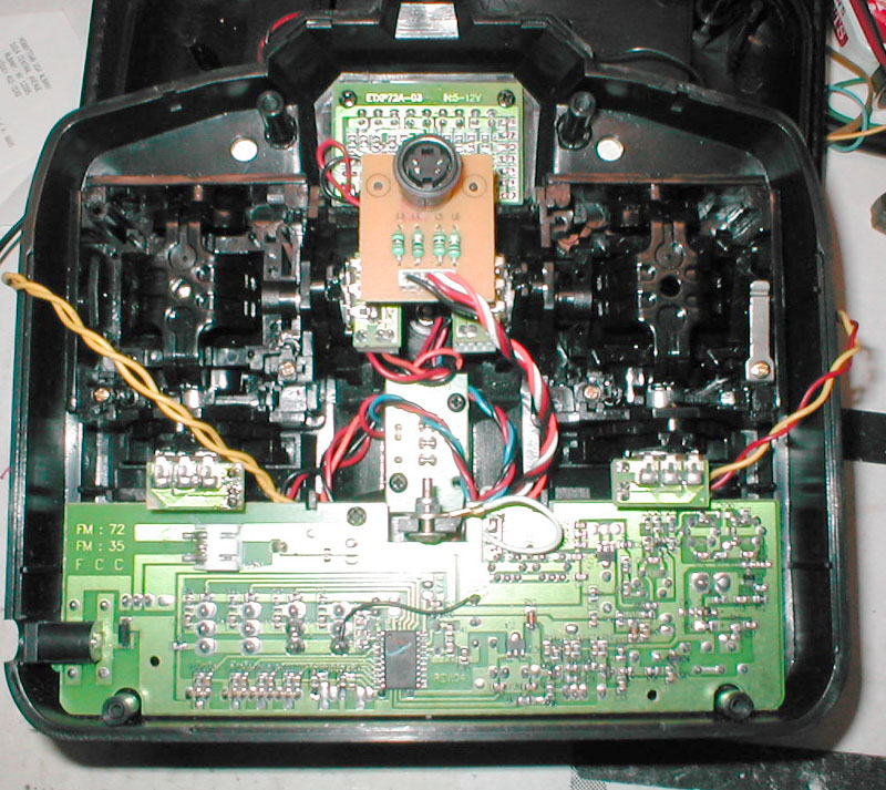
Step 1: Disassemble the transmitter
Remove the antenna whip by unscrewing it and pulling. Remove the four screws on the back of the transmitter. Gently pull the case halves apart. Unplug the red and black wire connecting the battery box to the main circuit board. You can now free the yellow leads to the TRAINER and IDLE UP switches and flip the back half of the case out of the way. You’ll be working on the front half. Gently lift the board holding the trainer cable socket and set it aside.
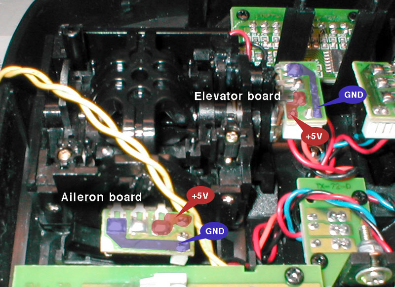
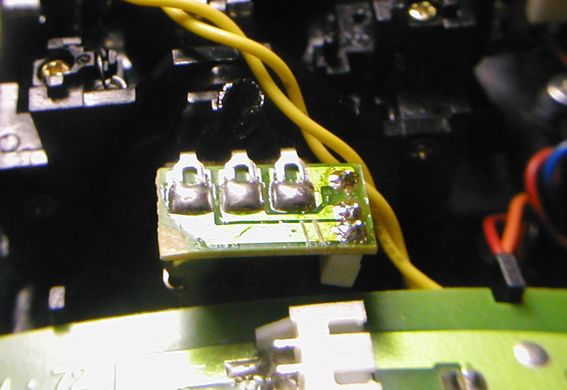
The two small circuit boards to the left are connected to the aileron and elevator pots. You will be inserting resistors into the circuit to reduce servo travel for those axes. The illustration at right identifies the boards and signals you will be working with.
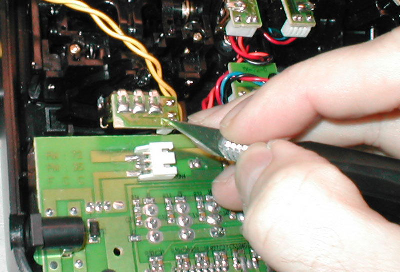
Step 2: Cut the +5V and GND traces on the aileron board
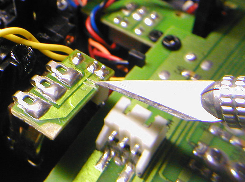
Use a knife to cut through the aileron ground circuit trace as shown. Make several light passes to avoid putting pressure on the board, because it can break loose from the aileron pot. It is not necessary to cut completely through the copper foil.
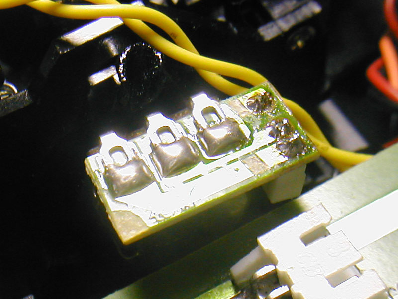
Make another cut about 1/16” next to the first one.
Use the knife to pry up the section isolated between the two cuts. Peel it loose and discard it. This effectively isolates the pot from the ground.
Repeat on the +5V trace.
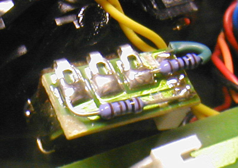
Step 3: Solder resistors in place
You should have picked out the resistors you want to use. If not, refer to this page for help in selecting them.
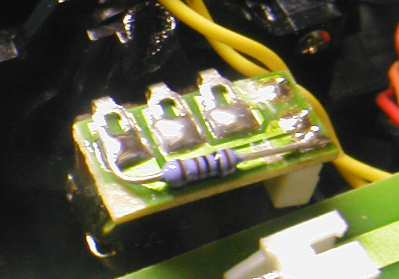
Solder each resistor across the gaps you made in step 2. One resistor should go from the ground terminal of the pot to the ground terminal of the connector. The other resistor goes between the +5V terminal of the pot and +5V terminal of the connector.
Use insulation pulled from hook-up wire to cover resistor leads; this will prevent shorting.
Step 4: Repeat for the elevator board
The elevator board is identical in layout. Cut the +5V and GND traces and insert resistors.
Step 5: Reassemble and test
Put the radio back together. Carefully route the switch wires so that they do not get caught in the gimbals. You will find posts inside the housing that you can wrap the wires around.
You will probably have to re-trim your swash plate mechanically after performing this modification. The trim range is also reduced by this mod. The trim levers on the transmitter may not move far enough to compensate for the effect of adding these resistors.
To reverse this mod:
Either remove the resistors and replace them with a wire, or simply bypass them with a wire. If you’re creative, you can install a switch in the transmitter to give you dual-rate on demand. Next time I will give detailed instructions on how to do this.
click to magnify
Instructions for reducing cyclic rate on BCP transmitter