 This isn't quite in order... it needs lots of editing.
This isn't quite in order... it needs lots of editing.
Its more an exersize than anything... I saw a couple of buttons at a convention which were miniture versions of those "scanvertizer" LED signs. I figured I could make one of those too... Only mine would be Cooler (tm).
Cooler how, you may ask. I dunno... its just an axiom. Mine is color (red/green, not full color) with 8 levels of brightness, and has a serial port. OH, and MSP430 chips have built in thermometers too... And, it has a movie camera speed check function.
Either way, I attempted to take some notes as I built it. So here they are.
The procedure I'm using to make the pcboard is the "blue stuff". Ask the google for "print-n-peel". One draws one's artwork on a convenient computer (I used the pcb program, found in FreeBSD's ports tree. It has interesting mouse idioms. For the record: no Microsoft products were executed in this project (Windows is not the answer, its the question. The answer is "No").) Then one prints the artwork wrong-reading on the blue stuff. Next, you use an iron to remelt the laser printer toner, so the blue stuff sticks to the PCboard. Then you dunk it in water to cool it off, pull the backing off, and there's your resist pattern. Unfortunately, it'll take sand paper to get it off after etching. Yes, this is the only reason why I actualy own an iron...
The pins on an MSP430 (LQFP-100 package, I think) are sufficiently close togather that my trusty old 300 dpi HP-2 printer couldn't draw it. (entertaining problem to have...) 600 DPI minimum. So, only one solution: use the printer at work...
The printer at work got violently ill on the blue stuff. It curved faster than paper does after the fusing roller, and got all tangled up. Unfortunately, there dosn't seem to be a straight paper path option on an HP5MP printer. Luckily the printer didn't get so violently ill that I was buying work a new toy...
After the printer mangling, I managed to get two viable images, on the second piece of blue stuff. (I repeated the artwork as many times as it would fit, in hopes of not wasting the blue stuff)
The first attempt at ironing, I set the iron's temperature to "wool". That reduced the browning on the paper I used between the iron and the bluestuff/board. (From my previous attempts making the video over twisted pair thing.) I then rolled a dowl under the PCboard to increase the preasure. That transfer failed completely. I'm thinking that the "lots of preasure!" idea is incorrect.
I have enough scrap blue stuff left over from the video transfer project (bad artwork) to try out transfering with low preasure. KJ feels that the weight of the iron would be more than enough preasure.
The second transfer was done with (arguibly) too much preasure, basicly the same way I did the lower resoltion video transfer project. I then reworked a bunch of the traces with an exacto-knife, and a sharpie. That got the board to the "viable" state, and I etched it.
The dumping it under water step before peeling the backing off seems very important. When you skip it, the toner isn't quite solid, and it pulls up instead of the blue stuff off its backing.
I then soldered on the MSP430 and the jtag connector. Before putting the MSP430 on, I put a "blink the LED" program in it. That allowed me to check that it was functional very easily after I soldered it. Then, I checked the the jtag interface, by re-downloading the "blink the LED" program. The jtag connector I'm using is a 1x6 pin header, instead of TI's 14 pin header. But, its pins 1,3,5,7,9,11 of TI's pinout, so I just put the TI connector on "wrong" and it works.
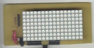
The next parts I assembled were one of the LED driver chips, and the crystal. I then put the LED array on by just sortof stuffing it into its holes, diagonaly, to get enough of a connection. Once I had gotten /something/ on the display, I properly soldered it. The LEDs are the most valuble part, due to the fact that no one seems to sell them anymore. I now have eight left...
The clock is being a problem. I thought I had standard watch crystals from digikey. But I could not order them as "watch crystals", so I ordered them as 32768 Hz 12.5 pf crystals, since that seems to be what "watch crystals" are. However, it dosn't start reliably. I'm also not getting timer interupts, since I'm trying to get them off of ACLK. I need to try running with MCLK and the rf osc, just in case I actualy mangled the MSP430.
Whats weird is that the crystal seems to run sometimes. I managed to get "Hello World" out of the serial port (holding a wire onto the pad, to a max323 on a breadboard, since I havn't put the max3232 chip on yet), and the baudrate clock was off of ACLK.
The clock problem has gone away, I finaly figured out what was going wrong. My opinion of the code and the compiler's opinion of the code differed, and I was immediately resetting the enable bit on the timer... But the USART didn't care (since it was not connected to the timer). So, I have a 32768 Hz watch clock. I'm multiplying that by 240 with the FLL module, to generate a MCLOCK of about 7.8 MHz. That is actualy out of spec, to run that fast I need a VCC of 3.6 volts, instead of my 3.0. Given 3.0V, the max speed is about 6.5 MHz, but I'm ignoring that problem for now (just say "prototype" and wave your hands). The USART is then generating its baudrate (9600 bps) from MCLOCK. The flash memory controler is also running off of MCLOCK, to get a clock rate of about 462 KHz. And last but not least, when in speedcheck mode, it gets a 24 fps * 8 Hz clock by diving Mclock by 256 in hardware, and then another 80 in the ISR, to get exactly 192 Hz.
I have 2 8x8 LED modules, they are red/green bi-color, so each modle is 8x16 common anode. With both modules, its 16x16 electricly.
The driver chips I have are 16 segment drivers, and 8 column drivers. The column drivers are the current sink, and the segment drivers are the current source.
If you can keep anode and cathode straight better than I can, you will note that they are backwards... common cathode. (DOH...)
So, I'm actualy going to be 16x16 electricly. One driver chip's 16 segment drivers will be one side, its 8 colum drivers 1/2 of the other side. The second driver chip will not use its segment drivers, and just use its column drivers as the remaining 8 columns. The final resolution is that there are 16 segment drivers, and 8 red colums, and 8 green columns, the two sets of column drivers are the colors.
With current wisdom, that was actualy not a good idea. I should have used the all segment drivers I already had. The problem is how many clock ticks do we have per LED, per frame, for pulse width modulation? If I had used both of the sets of segment drivers, I'd have gotten twice as much time for the PWM.
The display is run in an interupt service routine generated by the basic timer. The timer runs off of ACLOCK, divided by 4, so its at 8192 Hz. Each timer tick, the ISR shifts 16 pixels into the segment driver, and then hits the latch to update the segments themselves and goes to the next column. Note that little detail: during the ISR, while its shifting, the display is still showing all the previous values.
So, we get an entire frame every 16 ISRs, so thats 512 frames/sec. But, its doing pulse width modulation, to get multiple levels of brightness. So, we need a series of time ticks for each frame, for full brightness an LED is on for all of them, for half bright, its on for half and off for half. I selected 3 bits of brightness, so we need 7 time ticks (all dark is on for 0, so why have a time tick for it?). So, we get a real frame is 7 PWM frames, or 73 frames/sec.
There is a PWM "position" counter which is incremented each ISR frame. A pixel is on if its brightness is less than the PWM "position".
Now, there are two more tricks. One little problem with the pcboard layout is that its optimized to avoid jumpers. So, the logical layout of the pixels is not their electrical layout. So, I have lookup tables to convert logical coordinates to electrical coordinates. The tables cost ROM, but execute nice and quick.
Unfortunately, all those lookups are expensive when they are in an ISR which is being called at 8 kHz. So, the array which the ISR is reading the image from is actualy in physical order, not logical order. There is a second array which the graphics code writes to in logical order, then the function dispcopy does all the remapping as it copies the image into the ISR's frame buffer. Thus all the remapping is only done when the graphics code wants to update the display.
So, this is one of those nasty tradeoffs. Simplify the board layout, and complicate the code.
That double buffering is taken advantage of again for the smooth scroll functions. The software frame buffer is larger than the actual display, so it renders the text only once per character, then just walks the display along, util it hits the real edge, has to rerender starting at the next char.
So, now that we have a frame buffer, how do we draw the text?
The first idea was to get a 1 bit per pixel font. So, I went looking in the font directory from X, and found a bunch of bdf fonts. Asking the google resulted in a PDF file of the spec for BDF fonts. It was mildly disturbing that the spec referred to 650 bpi tapes. I then wrote up a perl script (readfont) which generated C code to build a font structure.
The 1 bpp font looked OK... but then the question was its a 6 bpp display, how about anti-aliasing?
So, time to play with freetype... I wrote the getfreetype program, which built a font struct for an 8 bpp font. The results however were remarkibly difficult to read. While the 1bpp font can be easily read relatively close, the 8bpp font could only be read from a significant distance.
Either way, the font structure was then compiled into the code as a constant. The const keyword is important. GCC will by default put initialized variables into RAM. If you specify it to be a const, then it will be put into ROM.
I then wrote a function named fontrender which given a font, a char, and some coordinates will draw the character into the framebuffer array. But, what text should we be drawing?
So, the evil plot... I'm going to cheat and assume the serial port is reliable. Then, to get 8 bit clean yet still be able to indicate EOF, I'm doing escape codes. They are based on C's string escape stuff, only a subset and it assumes HEX. Actualy due to code reuse, /all/ the numbers are in HEX.
If the assumption of serial port reliability turns out to be too optimistic, then perhaps fall back to xmodem. If nothing else it would be an entertaining blast from the past.
You've probably noted a vague similarity to Unix there...
When you say font or text, it goes into upload mode, and all the data you send goes directly into flash. IE: no line editing. When the file is done, a \x marks it. after the EOF, the CLI goes back into command prompt mode.
But, I'm getting ahead of myself...
The erase function is global because the flash can only be erased in 512 byte blocks.
Here's an important little detail... The flash memory controller needs a clock. in the case of an MSP430x449, that clock must be 257 to 476 kHz. The range is how quickly you want to write. There is a divide by 1 to 64 on the flash timing generator. So, run it off of MCLK (32768 Hz * 240) and divide by 17 to get 462607 Hz.
It has the idea of uploading records. So we have font records, and message records (anything else?). The records are consecutive 512 byte blocks in flash, the header has a type, a name, and a length (in blocks). On boot, and when a record is added, a directory of fonts and messages in RAM is built. Different messages are then selected using the use command or buttons on the button.
The consecutive blocks makes refering to structures easy, we just don't have to worry at all about skipping block headers as we walk down a structure.
To add a record, we walk the records, using a record's length field to get to the next record header. A freshly erased block reads 0xFF, so when we see that, put the next record there.
How do we want to handle executable stuff, to implement more modes? Current opinion is refer to them at compile time. Relocatable code would be hairy... And besides, the entry barrier is to get a JTAG interface, and just rebuild it. The sourcecode is either below, or will be when I hit version 1.0.
We can erase the flash in 512 byte blocks. So, thats the logical allocation unit. Then we put a next pointer on each block.
So, we start with a record header. It has the record's type, name, length, and next field. If thats the record we want to play with, then there we are, otherwise read the length field, and walk till the next record. If the next pointer is 0xFFFF (IE: the uninited value)
We have in the RAM memory, an array of pointers. The pointers then go to linked lists within each record written to the flash segment. The overhead of a full blown filesystem isn't quite realistic. Is it? 512 byte pages with a free pointer, and a next pointer. The free list pointer would need to be in flash...
An uninited flash page reads 0xFF.
Lets leave the 6x10 font in the static section, as font number 0. How do we want to walk the flash datastructure? walk it on boot, and load an array in ram?
A mode consists of:
I have also generalized the filesystem. It now just worries about record types, as opposed to actualy knowing what is text, what is a font, etc. (Which isn't entirely true, there is a switch statement which converts ints into strings for the CLI, but that could have been an array of constant strings instead.)
For life, the init function clears the display, and looks in the filesystem for image record number 0. If it is not present, it uses a built-in initial image. Otherwise it uses image record 0.
The frame function then gets called. It has a large automatic variable to keep the next state in. between frames, the entire state is in the frame buffer.
Life cells have only two states, alive and dead. Two states is boring, so I've made is so that a cell starts out "bright" when it initaly gets set to a state, but then fades off as it stays in a state. Dead cells start out bright red, then fade to black. Alive states start out green, then fade to yellow. So, a glider leaves a fading red trail, and a spinner ends up with a yellow center, and ends of alternating red and green.
So, to implement this mode, I have written three functions, declared another filesystem datatype, and written a filter for converting pbm files into button bitmaps. Now I need to rearrange the button bitmap code so its library code, and capable of dealing with 1 bpp and 8bpp images.