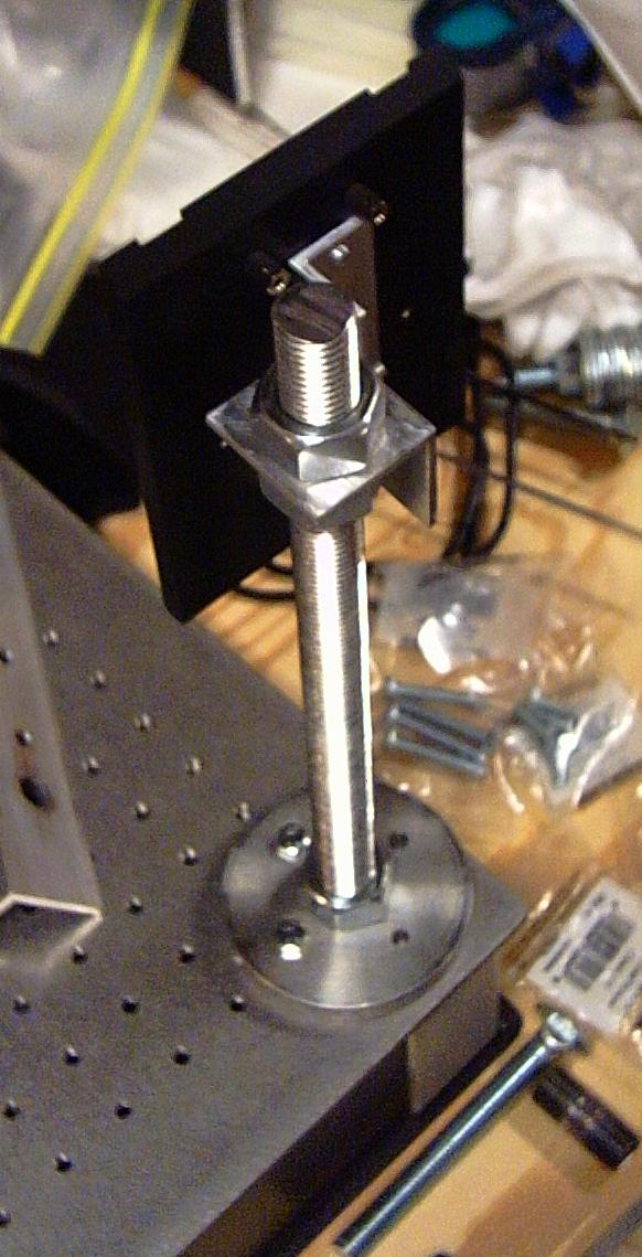
I am still using the same beam splitter assembly from version 2.2, however it is now held on a 1 1/2 inch square post instead of a 1/2 inch threaded rod. I believe this component finally addressed my vibration problems. The post has 1/4 by 20 holes every inch on all four sides, and one on top. I have fabricated three of these things (for the spatial filter, and object illumination lens), and I am so tired of threading holes.
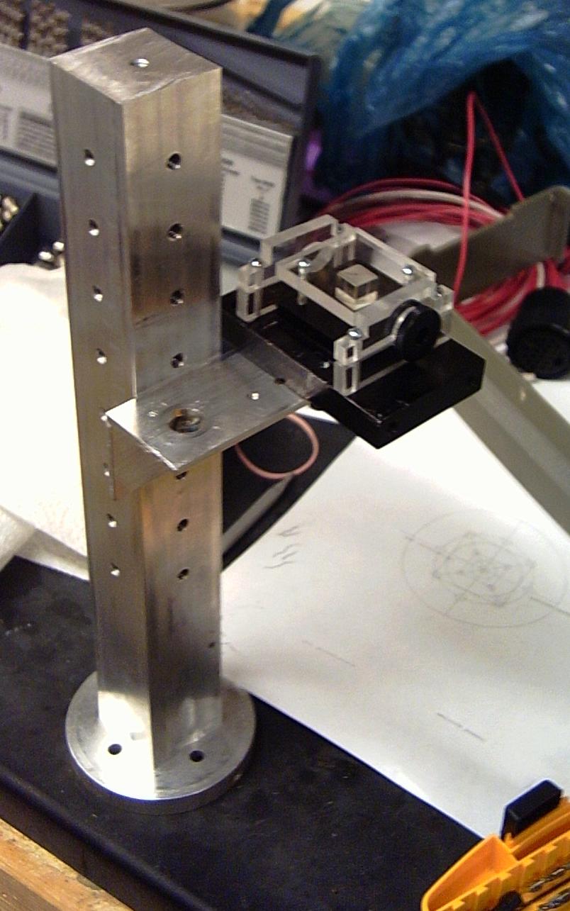
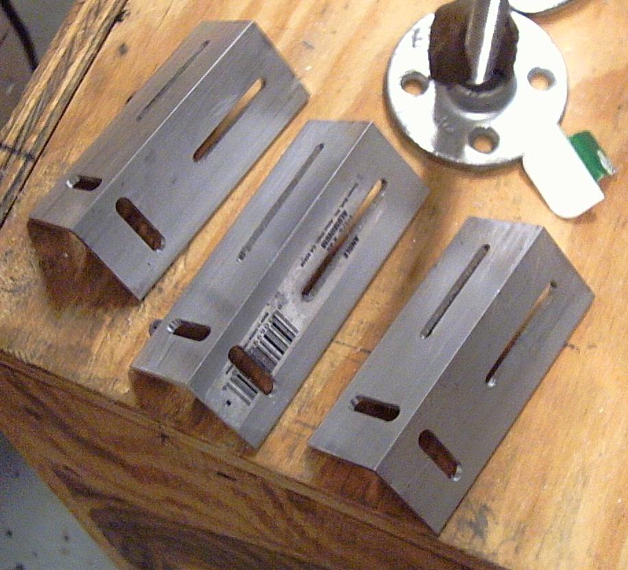
The beam splitter itself is on a 1 1/2 inch angle out-rigger. I have four of these arms, fabricated in my friend's milling machine. One slot allows the arm to move vertically along the post (optical Y axis), and the other slot allows the beam splitter (which has a #8 screw on the bottom) to slide closer and away from the post (optical X axis).
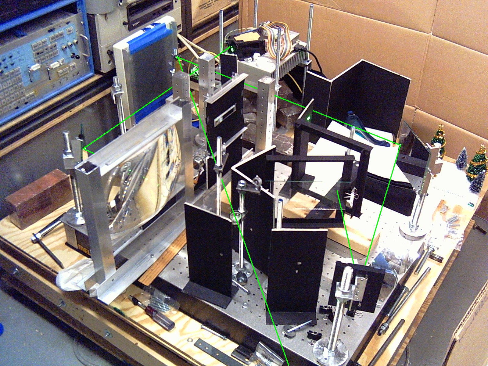
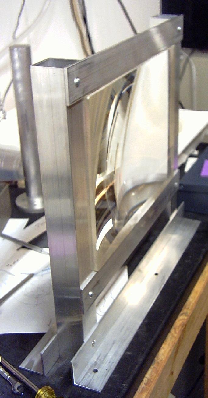
The beam splitter itself is behind a post (the uppermost one). Then one arm goes off the mirror on the left corner, which bounces the beam off the flat surface of the big collimating lens. The other arm goes off the steering mirrors on the top right and bottom right corners, and then bounces the beam off a piece of glass clipped to my H1H2 frame (see version 2.2). The arms then recombine at the beam splitter, bounce off a steering mirror to the left of the beam splitter, and go through a lens way at the bottom. (There are quite a few un-used optics on the table.)
The final interference pattern was then watched with a video camera, and a program I wrote which captures video, and adds the frames together. I then compared the interference pattern from a very short capture (2 frames) to a very long capture (100 and 1000 frames). Unfortunately, since the last mirror at the end of the arms is a piece of glass, the interference pattern was very dim and the video camera did not get a very good image. However it was visible, and significantly more stable than my previous adventures. I wouldn't call it rock-solid, but I've never managed to achieve that state...
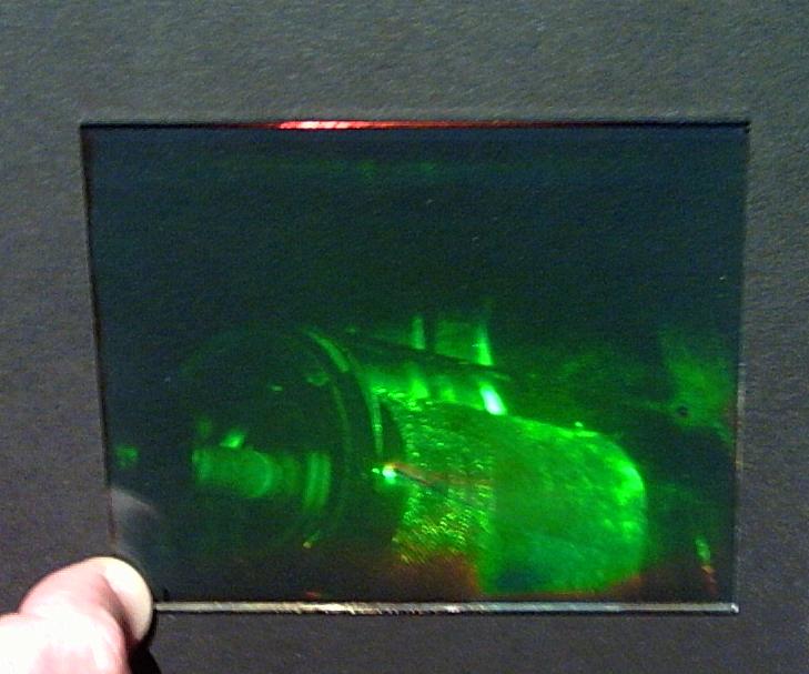
I then made an H1H2 hologram, number 32.1, and it is the first reflection hologram I've made which did not require fiddling with the colors in an image editor to see the holographic image.