The laser is an oscillator two amplifier laser, with a second and third harmonic generator. There are two capacitor charging supplies, one for the oscillator, and one for the two amplifiers. The two amplifiers each have their own capacitor bank (so a total of three capacitor banks). The charging supplies have independent voltage and trigger delay controls.
The oscillator thresholds at approximately 1.6 kv. I have it set to about 1.7 kv. There are two lamps per rod, electrically in series, with an arc length of about 4 inches.
The amplifiers are set to 1.46 kv. The amplifier rods are the same dimensions as the oscillator. One of them is intended to be an amplifier, and more heavily doped. The other is an oscillator rod salvaged from a different laser.
I have a DET10A PIN photo diode detector from Thor Labs observing the oscillator. One interesting detail was getting it to see both the pump light leaking out of the rod assembly and the laser light which is pretty much staying in the oscillator. I stuck a postit beside the brewster polarizer, so the dump light from the polarizer would shine on it and from there get into the photo diode.
I got a Gentec ED500 joulemeter off ebay. It was only slightly ablated... (-: It expects a 1M load, IE a standard oscilloscope input. There is a calibration tag on the back which claims it will emit 2.2 volts per joule.
I don't know how it responds to short pulses, mine are allegedly 23 nanoseconds. For now I'm taking its word for it. It reports that I'm getting 10 or 11 millijoules per pulse, I'd like to think its reading low.
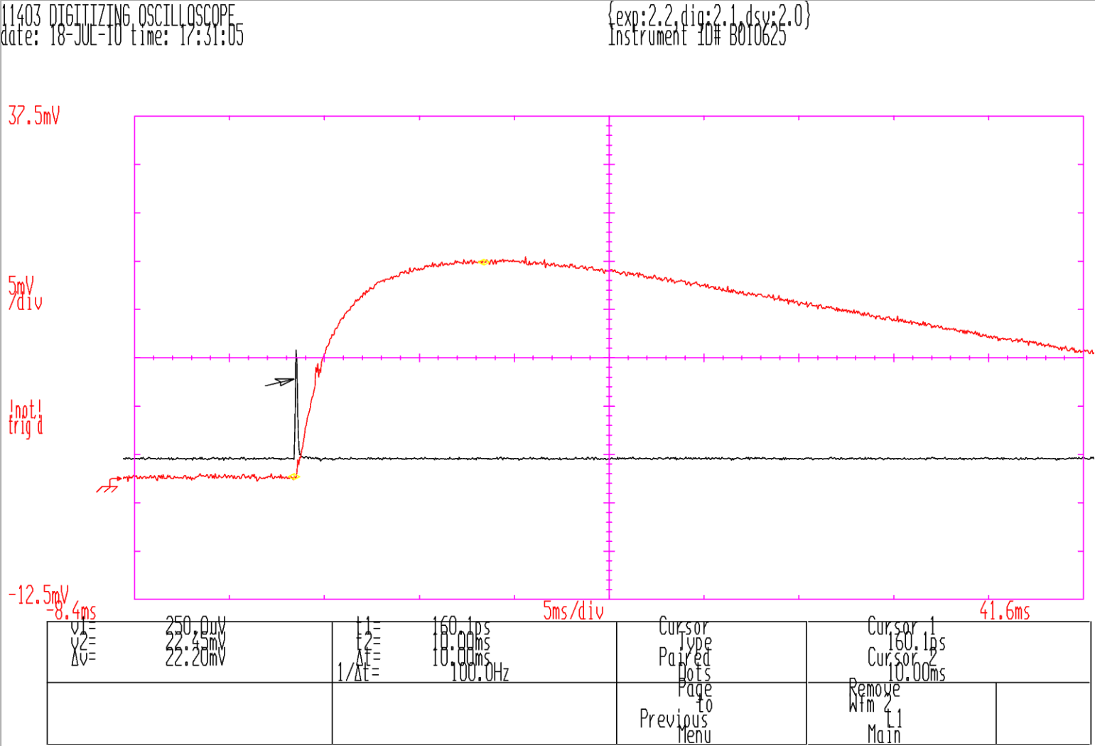
The black line is the photo diode showing the oscillator pump light. The joulemeter's response (orange line) is delayed about 42 milliseconds from the laser pulse.
For most of this effort, I used the joulemeter as the primary metric, doing a lot of tweek-fire-tweek-fire, trying to maximize the reading.
This laser has a passive q-switch, add pump light, and it opens when it is saturated. If the oscillator is "over" pumped, the laser will fire, then re-fill the population inversion and fire a second time. That could be useful for a multiple-exposure hologram, but the timing is probably not very consistent. I adjusted the lamp voltage to get a single pulse.
The joulemeter didn't measure a significant difference between one and two pulses.
If the amplifiers are over-pumped they may start oscillating on their own. If the voltage is OK, the beam looks clean (with zappit paper) but if it is too high there is a lot of extra stuff around the beam, and the joulemeter reads low. I put an aperture between the oscillator and the first amplifier, to reduce light spilling from the oscillator. That adjustment seemed to increase the critical voltage where the amplifier gets weird. I slowly increased the voltage, watching a joulemeter till it hit a maximum.
If the amplifier lamps are fired just before the oscillator lamps, the amplifier may be able to get a larger population inversion before the oscillator goes off. I set the oscillator to fire at 200 microseconds after the trigger, and then adjusted the amplifier timing from 100 to 300 microseconds after the trigger. I was not able to observe a dramatic effect though. I suspect the timing of my non-simmer-supply lamps is too inaccurate.
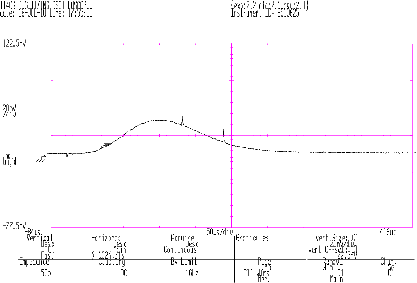
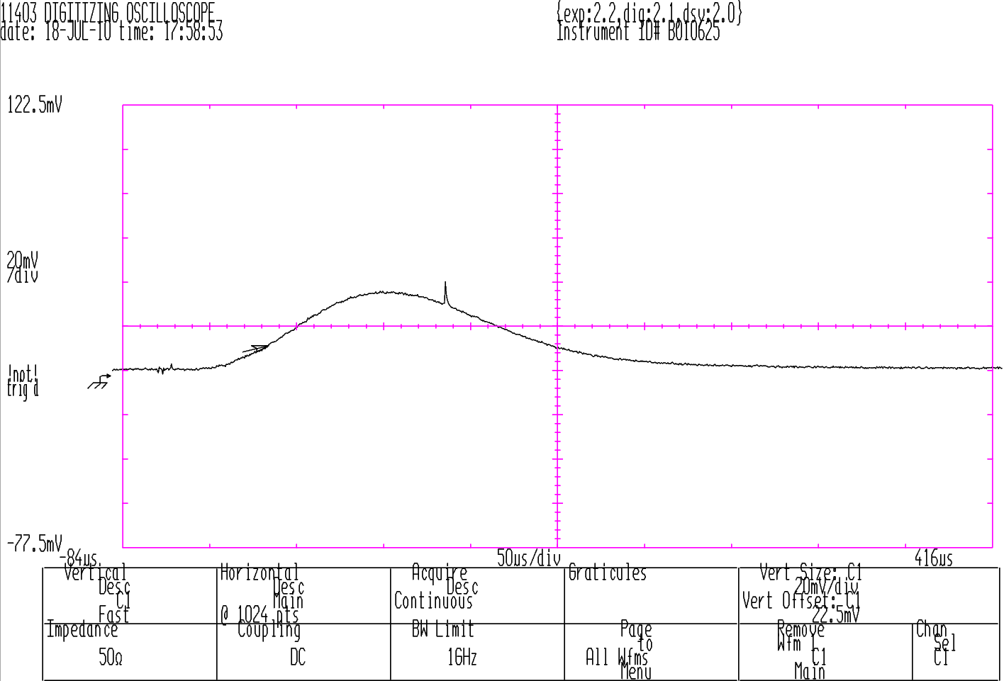
With a second photo diode, I could observe the timing difference between the lamps.
There are so many issues with the SHG...
I set one quarter-wave plate to make circularly polarized light, and then rotated a second quarter-wave plate, and observed the joulemeter for a maximum. I don't trust my instrumentation though. I've been aligning 1064 nm quarter-wave plates by calling them 532nm half-wave plates, and aligning them with visible laser and an analyzer polarizer. I need to get some 1064nm half-wave plates.
The SHG will only double light which passes through it at a specific and very small acceptance angle. My laser has a large wheel and reduction gear to adjust it. Finding the initial rough setting involved a lot of tweek-fire-tweek-fire searching.
The problem is detecting the second harmonic of a non-eye-safe laser, in an eye-safe manner. The pulse is too short for CCD video cameras to detect. I have an IR viewer which can see the pulse, but that can't tell the difference between 1064 and 532. One idea was to put it through a prism, its working when there are two spots (try it with a green laser pointer sometime... you can see the 532, 1064, and the 808 pump light in a halo around it). In practice that didn't work very well either. I finally used the laser's dichroic filters for picking off only the 532, observed it with the IR viewer, and got lucky.
Though a cam-corder, the spot is invisible. It occurs between the pixels. But the flash is visible as a sort of background wash of color.
Raw Imagery: 20100718, 20100724 (holography attempt)