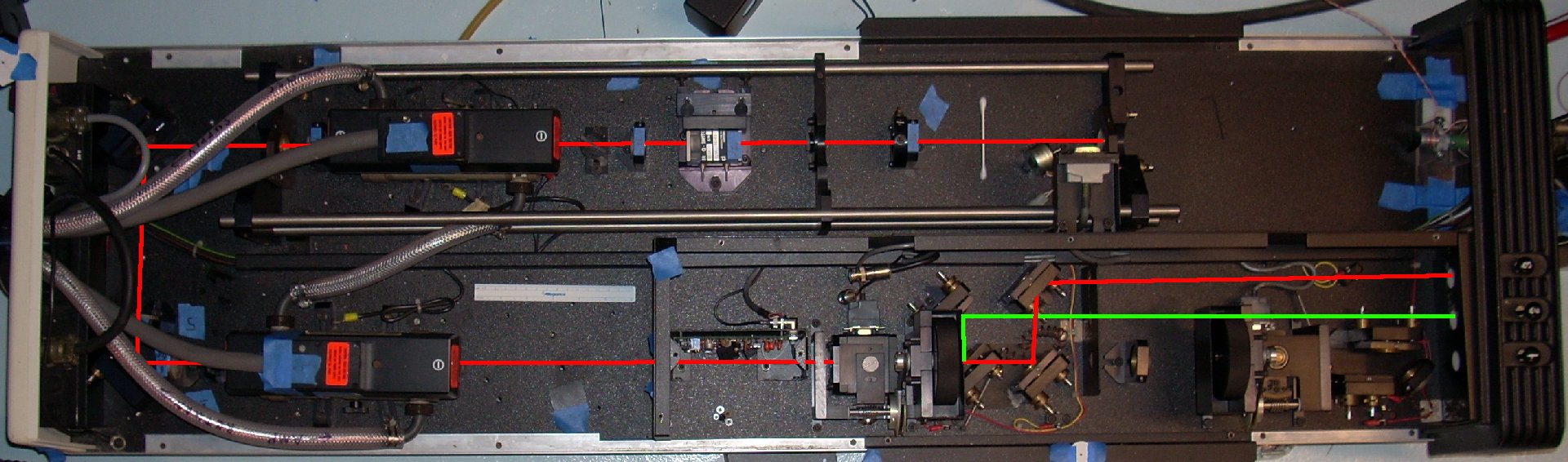
Red is IR, Green is 532nm. UV is not shown yet.
The laser is an oscillator-amplifier YAG, with second and third harmonic generators. Both rods are 4 inches by about 1/4 inches, and pumped by two linear flash lamps (5mm bore? OD is 7mm.) each. There are two movable assemblies on the right side (down stream) of each of the harmonic generators. They hold filters and mirrors to pick out the different frequencies. As shown the 532nm one is "up" and the UV one is "down". If both are down, then all three frequencies will come out of shutter number 1.
I made some alignment disks (postscript file here) with 1/8 inch holes punched in the center. The disks fit into the optics mounts, and can be easily removed by poking at them with a piece of masking tape.
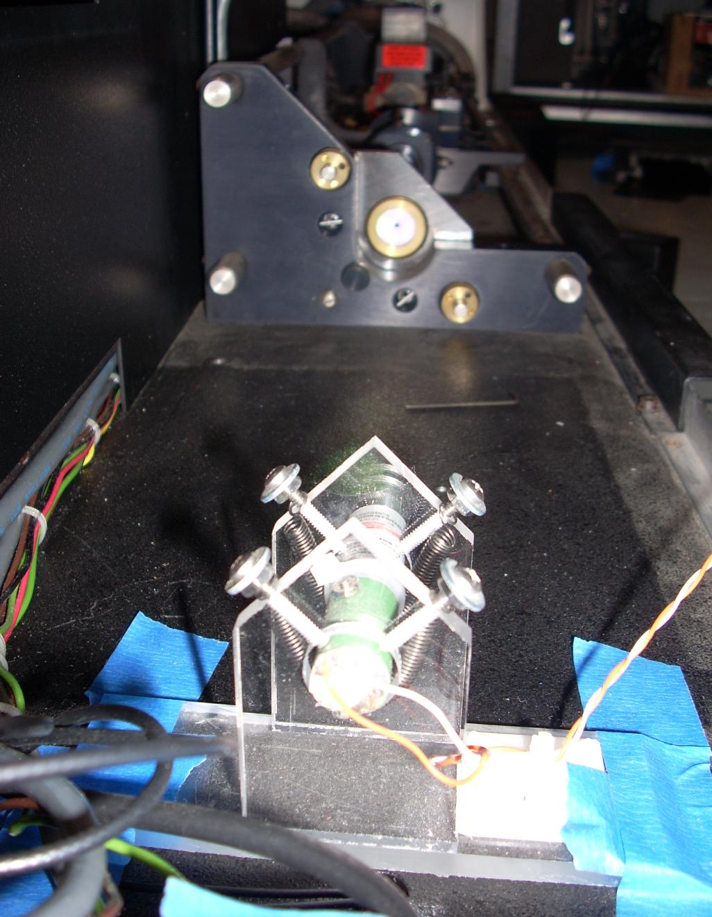
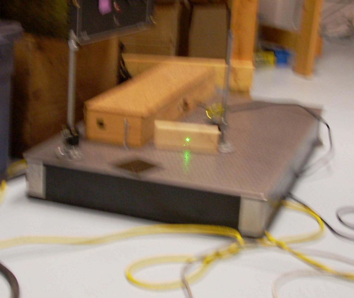
I then built an alignment laser with a laser pointer in a positioning frame with some 4-40 screws for adjustment. To make the screws easier to turn, I put a washer immediately below the head, with a nut holding it in place. I then stuck a pin hole on the front of the laser pointer to make a very small (1/32 inch?) beam. In the picture, the alignment disk can be seen on the high reflector. The orange sticker in the distance is on the rod power connector.
The resonator is about 800 mm long, and consists of three Invar rods holding the high reflector (HR), a lens, and the output coupler (OC). The rest of the optics (in order from the HR: aperture, q-switch, quarter wave plate, polarizer, rod, quarter-wave-plate, OC) are not mounted on the invar, but are instead just bolted to the optical bench.
In that arrangement, the laser can not possibly lase. The polarizer and quarter wave plate are reversed. In that arrangement, the q-switch will not be able to allow the resonator to resonate.
If the quarter wave plates are positioned on each end of the rod, they will cause the light to be circularly polarized within the rod, which eliminates spatial hole burning. (The standing light wave in the rod will only "use" the atoms which are not in the nodes of the wave, the circularly polarized light does not have nodes (it instead looks like an auger.)) (Solid State Laser Engineering, 6'th edition, page 265)
I suspect there was a failed attempt to retrofit the quarter wave plates to avoid spatial hole burning.
I taped the alignment laser down at the end of the high reflector, and adjusted it to pass through the holes in the alignment disks on the high reflector and output coupler. Then I adjusted the high reflector so the reflection off the resonator surface (as opposed to the back surface) went back into the alignment laser. I had about 6 inches of distance between the two, I would have preferred more, but thats where the optical bench ended. There were actually two reflections off the HR. It is just slightly concave, and the alignment beam wasn't quite on its center. I guessed on which one to use, and had to switch back and forth a few times before it would lase.
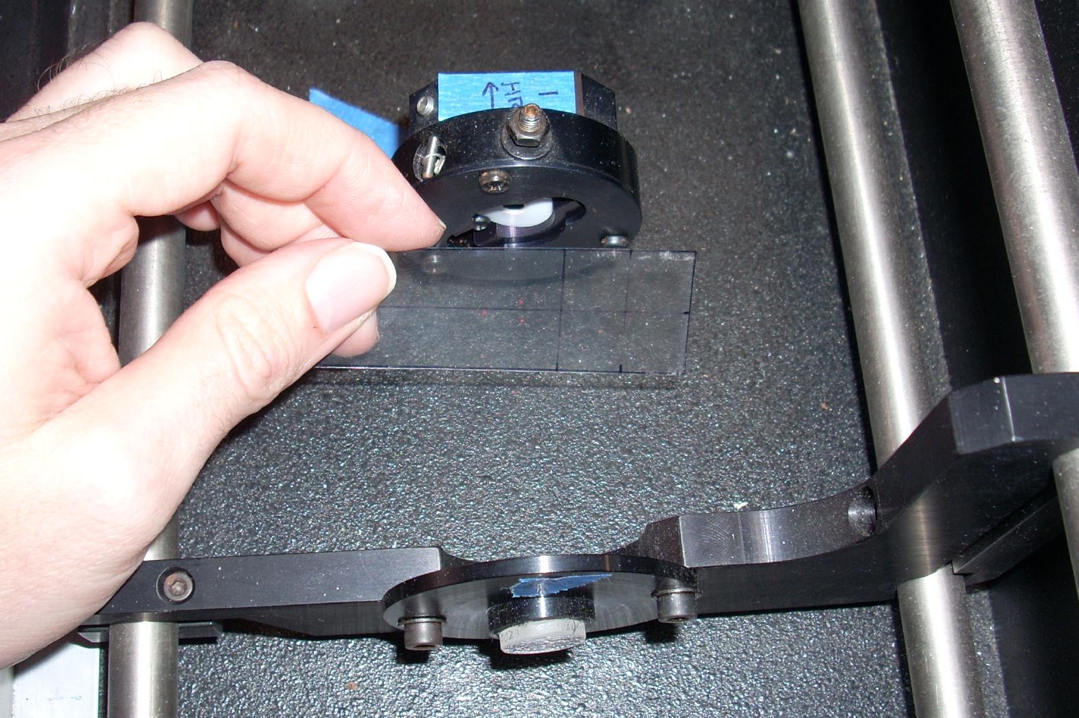
I usually looked at the reflections by holding a piece of laser printer transparency film in the beam. It scattered the beam a bit, making a spot on the film. Changing the angle of the plastic changed the relative brightness of the "up stream" beam and the reflection off the optic "down stream". Another result of the scattering is that when looking at the end of the rod or other "large" optic, the scattering illuminated its entire diameter, and reflected a large disk onto the film.
I then repeated that process for the lens, q-switch (not running at this time), and output coupler. The lens is on a wedge so its reflection did not line up. It also had several reflections off its front and back surfaces, and I centered the lens on the alignment beam by lining up all the off axis reflections with each other.
I centered the beam on the rod by fogging the ends with my breath, and then moving the rod assembly in its mounts. I'm not sure thats very good for the anti-reflection coatings.
I then started firing the flash lamps and looking at zappit paper. The rough alignment actually got a really nasty looking beam, when the alignment disks were removed (they act as a 1/8 inch aperture). I tweaked the mirrors to get a good blob in the middle, and then put the alignment disks back in, and tweaked it closer. The Laser FAQ has a good description of the procedure, search it for "walking the mirrors". With the alignment disks in, the beam looks like its TEM00, but the math says that would require a 0.9mm aperture, not the approx 3mm one it has.
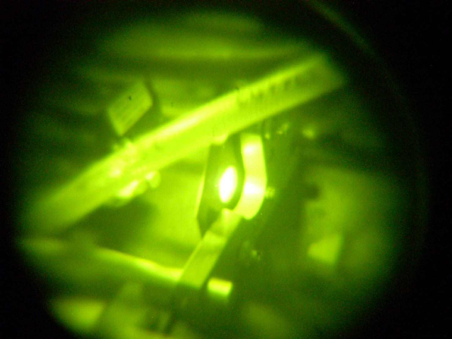
At this point, I got some green out of the frequency doubler. It doesn't look like much... but it was a milestone. There was a bit of confusion at first, I typically watch the laser through an IR viewer, so as to actually be able to see the beam, and the viewer is inherently eye-safe, but it makes everything green. So I looked at it through a cam-corder, and saw the green. I do have some 1064/808/532nm goggles, but they are only OD of 2 or so.
All the original marks for the fast axis of the wave plates had been erased, by cleaning efforts.
So... how does one find the fast axis of the wave plates, preferably using visible light instead of IR? The Enlightenment (tm): a quarter wave plate for 1064nm is a 1/2 wave plate for 532nm. And a 1/2 wave plate rotates the polarization of a linearly polarized beam 0 to 90 degrees as its fast axis goes from 0 to 45 degrees relative to the polarization (That only narrows it down to one of two 90 degree angles though).
So I assembled a light meter, a polarizing cube beam splitter (used as an analysis polarizer) one of the mounts for the quarter wave plates, and a polarized CW frequency doubled YAG. Without the wave plate in position, the laser beam passed through the analysis polarizer. I then rotated the quarter wave plates in the laser beam such that the reading on the light meter was minimized, and marked the edge.
Aligning the amplifier was about the same as aligning the resonator rod. The interesting part was the steering mirrors between the two. The thing to keep in mind is that if the angle of the beam is wrong adjust the second mirror, and if the position of the beam is wrong adjust the first mirror.