After I don't know how many months of fabrication, I made my first multiplex hologram today (2005.10.22). Whats even more amazing is that it actually came out...
The term "holographic stereogram" would actually be better. It is a hologram consisting of possibly hundreds of small holograms, each of a 2-dimensional image from a different point of view. The small holograms are vertical strips, and looked at together, present different images to each eye to get the 3 dimensional effect.
Or, thinking about it another way, if you take a normal transmission hologram and shine a narrow beam of light on it (instead of illuminating the whole thing) it will project a 2 dimensional image of the scene in the hologram as if the narrow beam was the pin hole of a pin hole camera located at that point on the hologram. A multiplex hologram does it the other way around, putting separate holograms of 2 dimensional images at each point on the hologram, to build up a complete 3D scene.
Ideally, there would be a separate 2D image and hologram for each point on the plate, in a grid pattern, but thats a lot of holograms. So to save time, vertical strips are used, and there is no vertical parallax. That also works well when the final hologram is a rainbow hologram, since they also have no vertical parallax.
Initial mechanical assembly started on April 2, 2005.
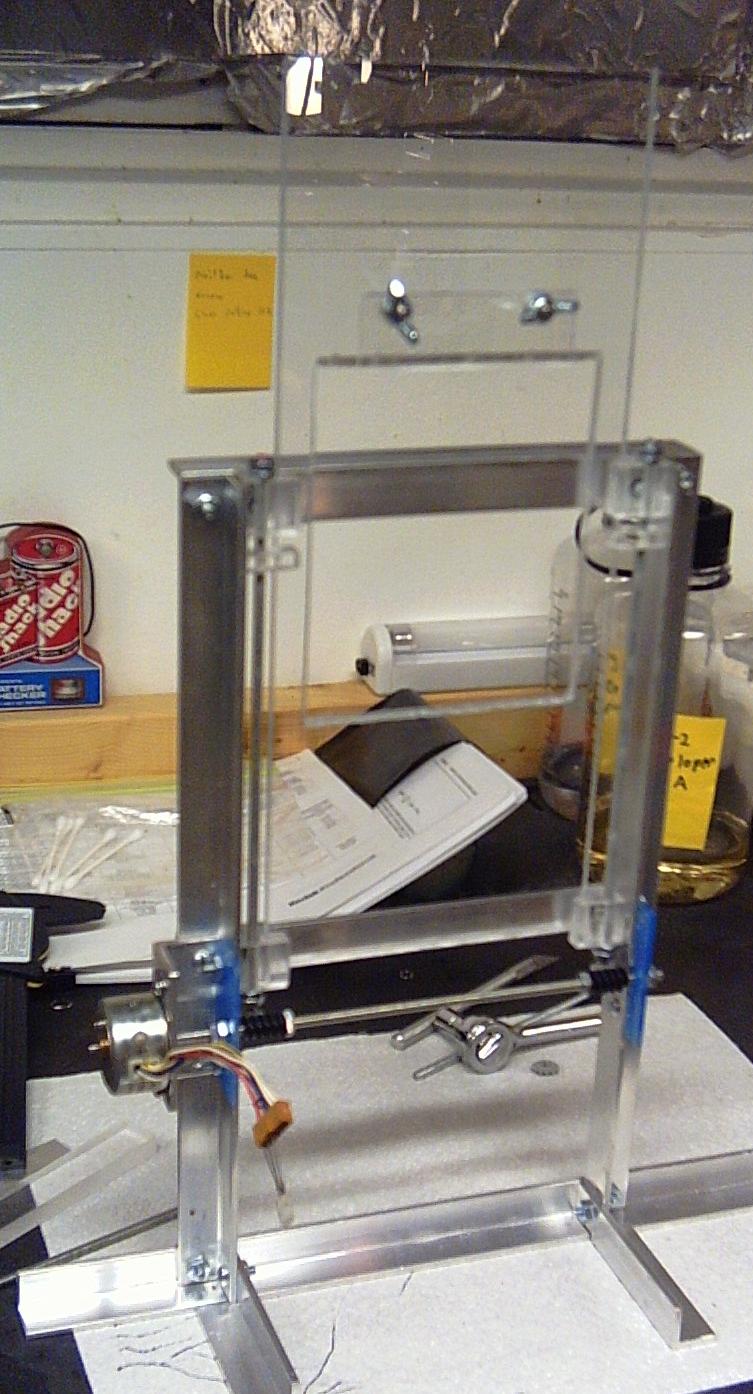
The plate holder moves the plate, behind a mask, to create the separate strips. I moved the plate vertically, so my reference beam (which comes from "above" the hologram, to make lighting the final hologram easier) hits the plate from the side, and I don't have to have overhead optics.
The plate is a standard 4x5 inch glass plate held in the middle of the plate holder, on a sliding piece which is moved vertically with a pair of threaded rods (one on each side.) The sliding piece is made of 1/4 inch thick Plexiglas, and may at first appear too long, however, its length is needed so the ends don't fall out of the L shaped bits which hold it against the aluminum frame.
The two vertical threaded rods are then driven by a single horizontal threaded rod, which has a worm gear for each vertical rod, and a motor on the end.
The threaded rods are #8 sized, which is very close to the size of the shafts used on legos. The gears are lego gears, which I threaded with #8 threads, and then hold in place on the rods with jam nuts. I had to get a spiral fluted tap though. Lego shafts have a + shaped cross section, and a standard tap just fell into the spaces.
The plate is held in a groove on the bottom, and a 1/2 groove on the top, with a piece of Plexiglas making up the other half of the groove held on with wing nuts. The wing nuts are threaded onto #8 flat head screws which are in countersunk and tapped holes in the Plexiglas to keep them from moving, or blocking the plate from sliding.
Alignment of the gear train was a pain in the neck. My final design was to have the various mounting screws in slots, position everything correctly (The distance between the worm gears and the gears at the bottom of the vertical rods was touchy), and then tighten the screws. The blocks the threaded rods went through also need real bearings, or at least bushings so the threads on the rods do not catch on the plastic.
The primary difficulty was keeping the two vertical rods in sync. Followed by coupling the motor shaft to the threaded rod. I at first had a plastic cylinder with a set screw epoxied to a #8 nut, however the set screw kept slipping, and then stripped the threads out of the plastic. I then replaced that with a piece of 1/4" inch diameter aluminum rod, with a hole through the center and a set screw on one side of the motor, and a larger center hole, tapped for #8 on the other end, held to the shaft with a jam nut. One trick for keeping the threads in a hole normal to the surface of the material is to put the tap into a drill press, and then pulling off the belt and moving it by hand. (This is not my idea, I'm not sure where I read it though...)
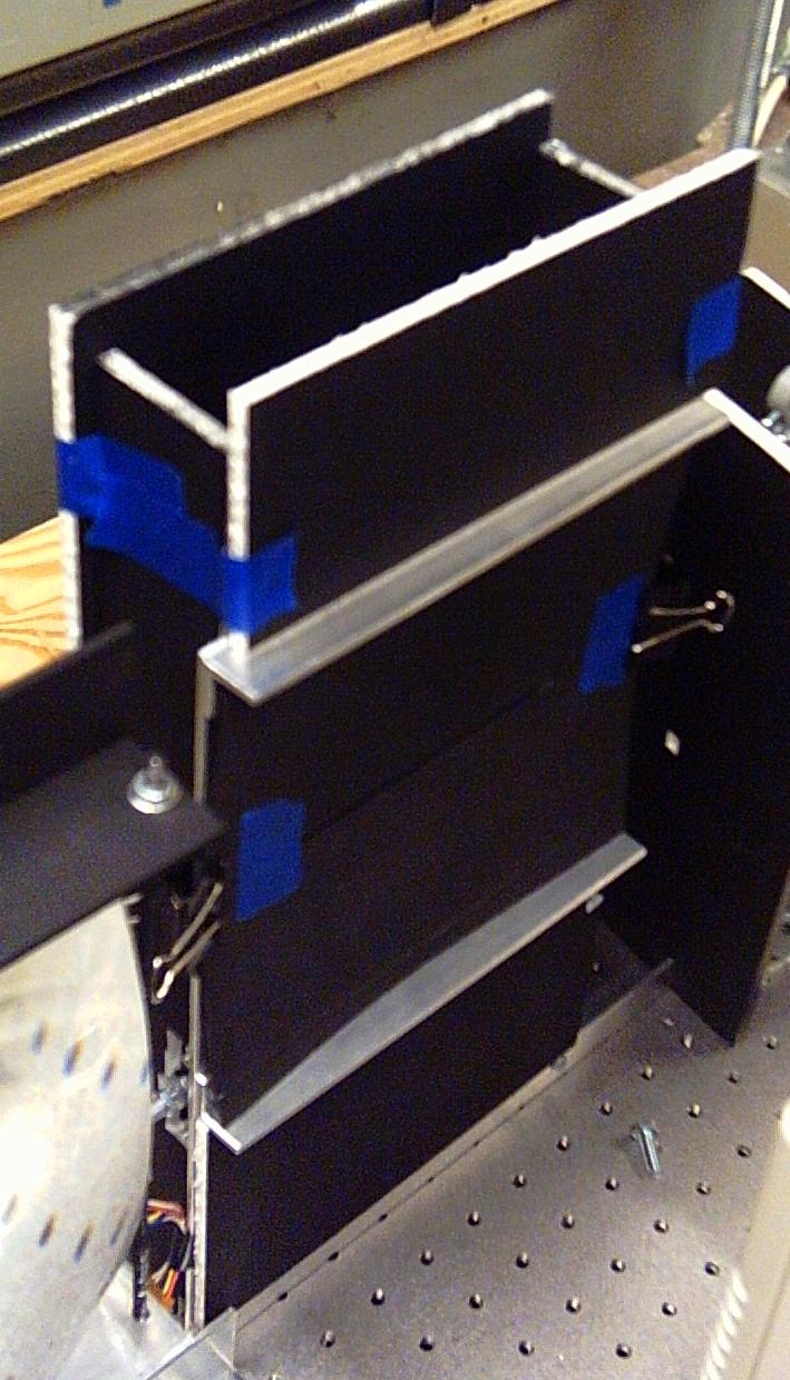
The entire thing was then surrounded with baffling made from foam core which had been painted flat black. The slit to mask off the plate was made from poster-board, spray painted black and then held in place with binder clips (to adjust for different widths.) To set the slit, I taped the two pieces of poster-board together the right distance apart on the bench where it was easy to measure them. Then the whole assembly was put onto the plate holder, lined up with the top edge of the plate, and clipped.
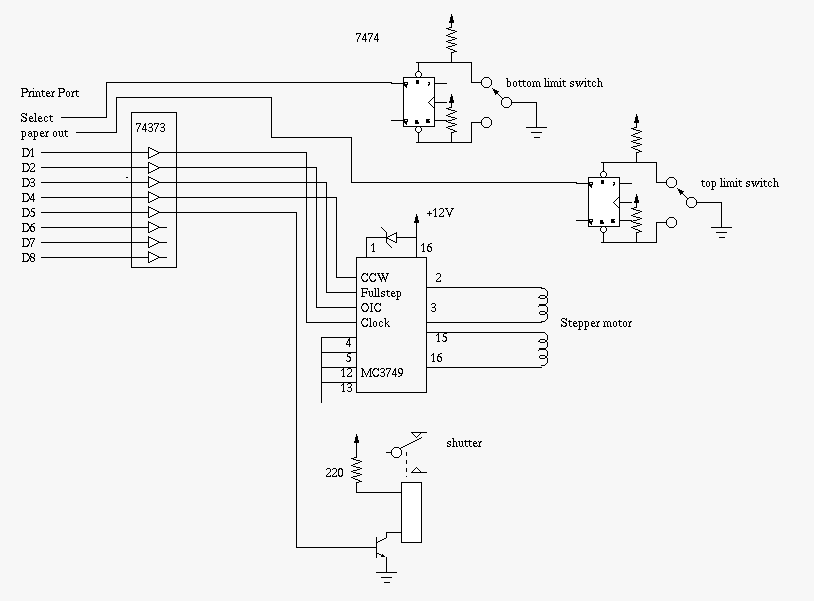
The circuitry to drive the plate holder was finished more or less on October 10, 2005. (If being on a breadboard counts as being finished...)
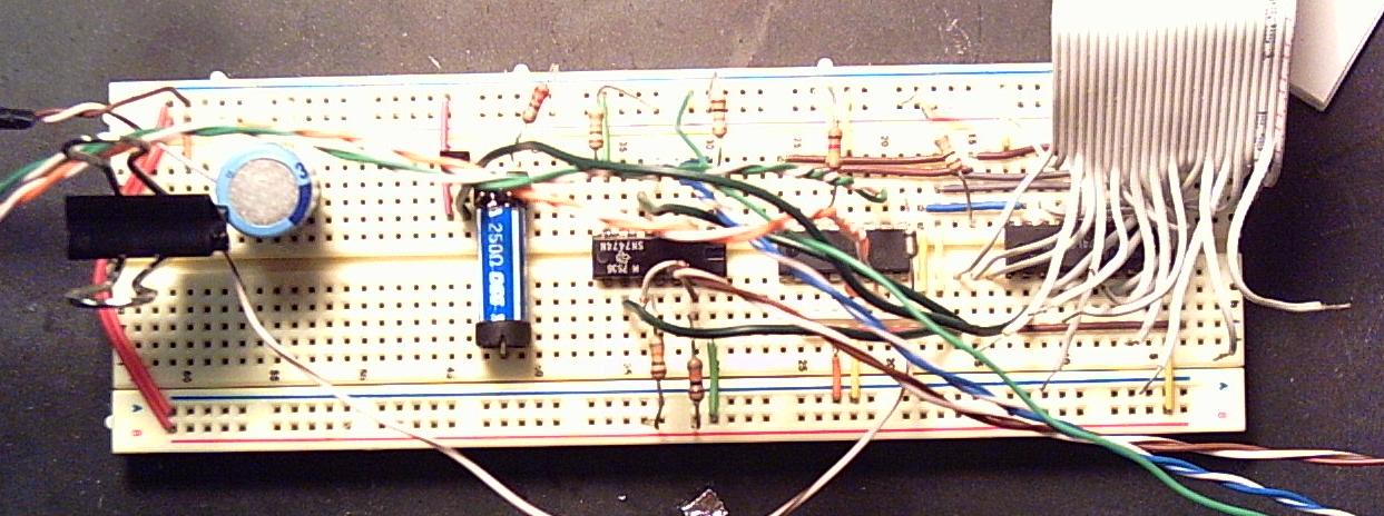
The motor (on the left side of the plate holder, above) is a stepper motor which I found in my junk box. It is driven using a MC3479 stepper motor driver chip from digikey. There are limit switches at the top and bottom (not in the picture above), which each have set/reset flipflops to debounce. Finally, there is a reed relay and transistor for driving the shutter input of my laser.
The entire thing is driven off a printer port. The computer generates all the timing for the stepper motor (the driver chip takes a direction, and a clock as input).
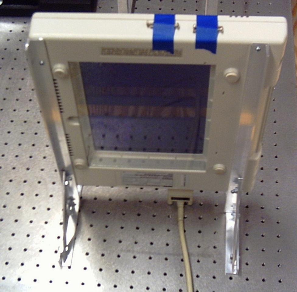
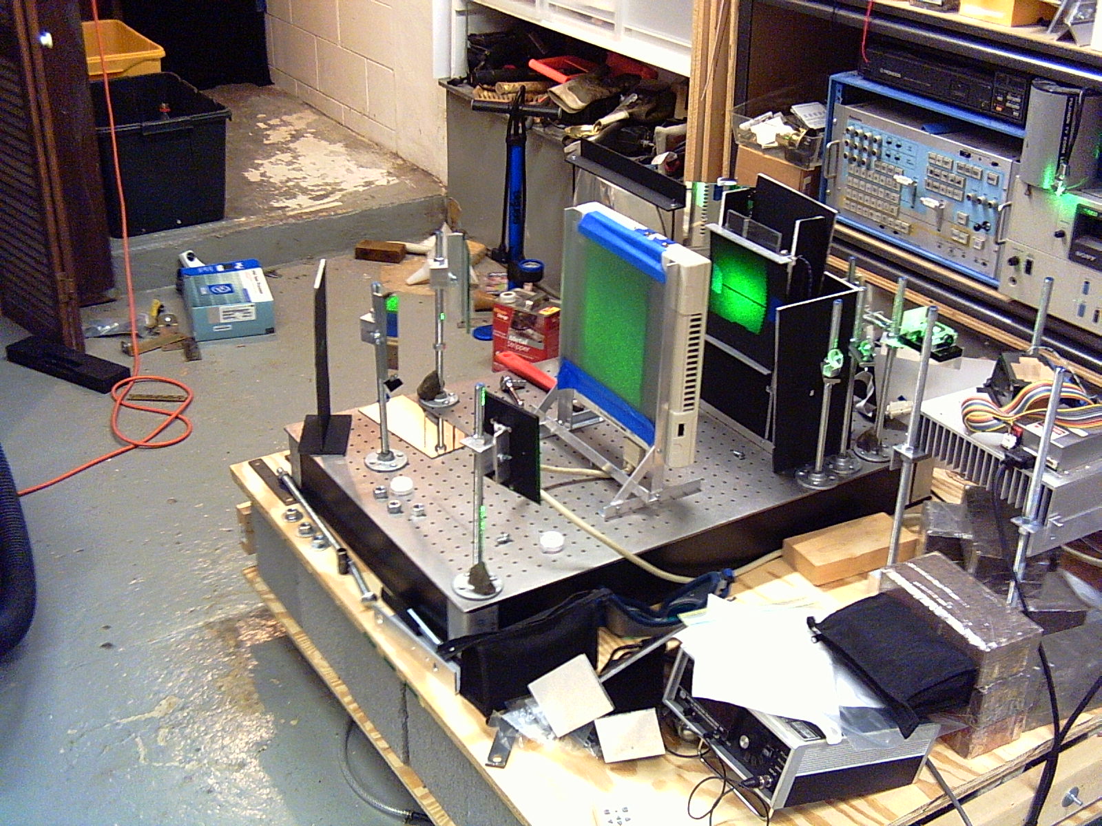
The LCD panel is intended to sit on an overhead. After poking at it a bit, it really wasn't possible to disassemble it very far. The width of the frame does block the reference beam though, forcing a greater spacing between the plate holder and the LCD panel than I would prefer. (It is about 9 inches, I was hoping for more like 5.)
I built a frame to hold the panel vertically, and attached it by replacing the screws which held its case together with longer screws which then reached through my aluminum frame. The original screws are taped to the top of the panel, in the hopes of not losing them...
The panel came from a surplus auction, and is a VGA resolution monochrome display. The monochrome is advantageous, in that the color filters from a color display would cause 2/3 of the pixels to be extremely dark, however it is only capable of 3 brightness levels. (Posterization in 3D looks really bizarre.)
A diffuser was then taped onto the "back" side of the panel. In addition, the panel is a polarizer. My laser is already polarized, so its redundant and costs a lot of light, but having the laser's polarization not matching the LCD panel's polarization cost even more light...

Frame 25 (The center one (well, the right center one).)
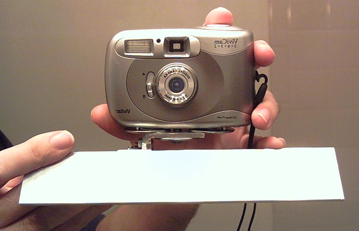
The source images were taken with my thumb nailer, an incredibly cheap digital camera I use for taking pictures of things in the lab (it was used for all these images, thus the poor focus, etc.). That slightly complicated taking pictures of the apparatus, since the camera was part of it...
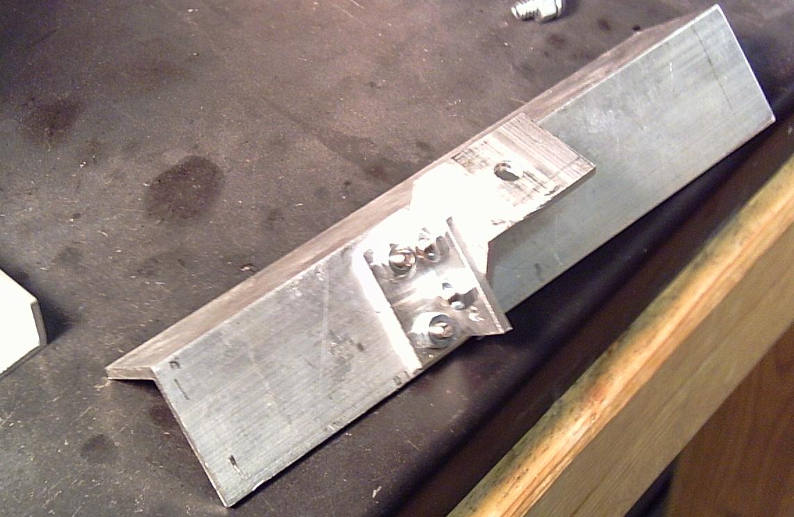
The camera was attached to a carriage made from 1.5 inch aluminum angle. It then slid along another piece of 1.5 inch aluminum angle which was mounted on a tripod.
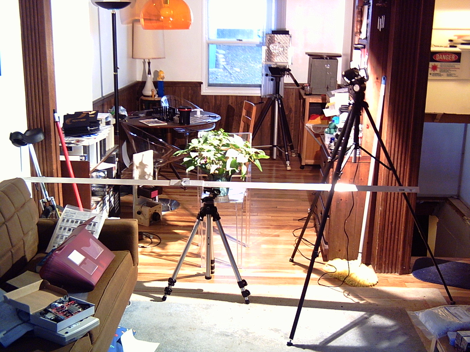
The rail is 8 feet long, it being easier to use part of a large rail, than extending a small one later... My subject is a poinsettia I got for Christmas last year (not dead yet. :-) I used a small light source, to get sharp shadows (hopefully more interesting). Cameras, especially cheap ones, are so much happier with lots of light...
The camera traveled about 6 inches on the rail, I took a picture every 1/8 of an inch, and ended up with 53 images. I ended up using the first 50 of them, and a 1/10 inch wide slit.
The software was written in C and shell-script. The display was driven with XFree86, and the images put on the root window using xv. (I unfortunately forgot about the X cursor... It can be seen moving very strangely in the middle of the hologram.)
A testit program just ran the plate holder up and down, hitting the limit switches. It was used to calibrate how far a stepper motor step moved the plate, and test that the plate holder wouldn't get hung up on anything. Turns out the step size is about 0.1 mils, however there is a vast quantity of slop in the mechanics, so that number is pretty much useless.
The final hologram was done by going to the top, and walking down. Thus it always "leaned" on the gear slop in the same direction, and was remarkably accurate. My friend Dan suggested printing the slit on transparency with a laser printer, to get better precision, however the transparency material is probably optically active. Perhaps a slit can be etched from a laser printed resist.
The initial settling time was about 600 seconds. It then did a 34 second exposure, waited a second, moved the plate, re-settled for 40 seconds, and did the next exposure. The 40 second exposure was probably a little short, based on a little brightness variation between the strips. So the entire 50 strips took a little over an hour to do.
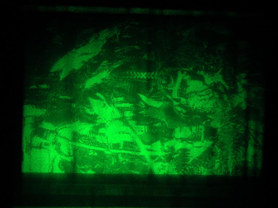
(Image by Ryan Dewalt)
My thumb nailer has never been able to get a good picture of a hologram. The brightness contrast between the image and the background is always too great. Ryan has a better digital camera... (The X in the middle of the image is the X Windows cursor, I had forgotten about that little detail until I looked at the finished hologram.)
These files are Copyright 2005 Tommy Johnson, and distributed under the terms of the GNU Public License.