This is a redo of a previous attempt last summer. While the attempt last summer did in fact work, it was incredibly scary to use. Then a great many other things happened... but now this project is back at the front of the queue.
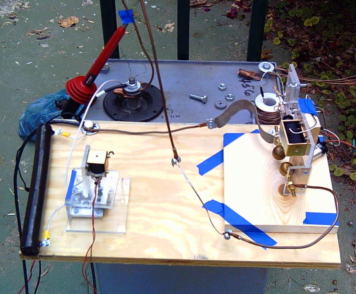
So, here's the goal: generate a large pulse of electricity through a coil wrapped around a pop can, such that the induced magnetic field in the can repels the magnetic field from the current in the coil, and crushes the can. Preferably without hurting anyone...
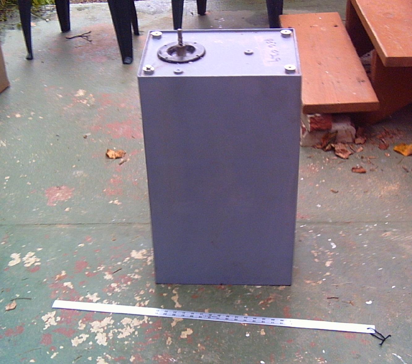
The pulse is generated by charging a capacitor, and then abruptly discharging it into the can. However, most capacitors can't deal with very abrupt discharges. They have a high internal resistance, and when abruptly discharged more or less get in their own way (and die, generally explosively). So I got a pulse capacitor, which has a low internal resistance, and is designed to do this. Its weighs a little over 300 pounds. Is mail-order not wonderful? I've never had to get something shipped freight before...
Note the piece of wire across the terminals.
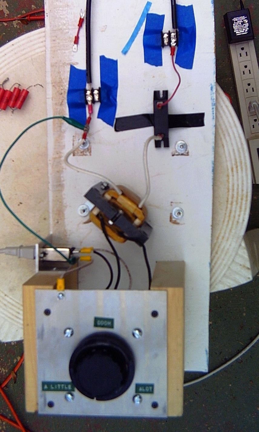
The capacitor is charged using a transformer intended to power a small helium-neon laser. It puts out about 2700 volts DC (after rectification). It is connected through a variac, to select a voltage between 0 and 2700. The variac is labeled "Doom", and goes from "a little" to "a lot".
The charging power supply was about 8 feet from the capacitor, next to where the operator was. The wire leading from the charging power supply to the capacitor is 15 kilovolt neon sign wire. Its also called GTO wire, should you want to ask google about it. Standard house wire insulation is only rated for 600V. Due to the expense of the high voltage stuff, most of the rest of the apparatus is put together with carefully spaced house wire. The discharge path is 4 gauge bare wire.
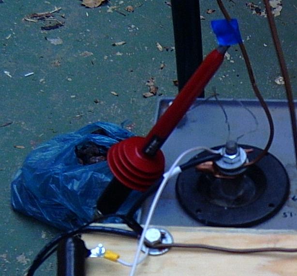
This is a high voltage probe, used to measure the voltage on the capacitor. Its a remarkably high resistance resistor which forms a voltage divider with a multi-meter's 10 megaohm input resistance, and divides any applied voltages by 100. It is connected to a multi-meter on the ground beside the apparatus. Its usually referred to as the soldering iron of justice, due to its comic-book-like shape and color.
If you look at the capacitor terminal, you will see the shorting wire is still there. I removed it shortly before beginning the experiment itself.
If things go wrong, or one changes one's mind, the capacitor can be discharged using a "dump switch". The dump switch is normally closed, and held open by a wall wart power supply. Just turn off the power, and the charge in the capacitor goes away.
The contacts are made of graphite intended for drawing. When the contacts are mangled by the electricity, they are easy to replace. The only problem is that its extremely messy to cut.
There is a 20K resistor in series with the dump switch, so the capacitor discharges slowly. Its the large brown cylinder behind the dump switch. It will dump 2700 volts (down to 10V) in about 30 seconds. I might drop it to 10K, but its nice to not stress the dump switch.
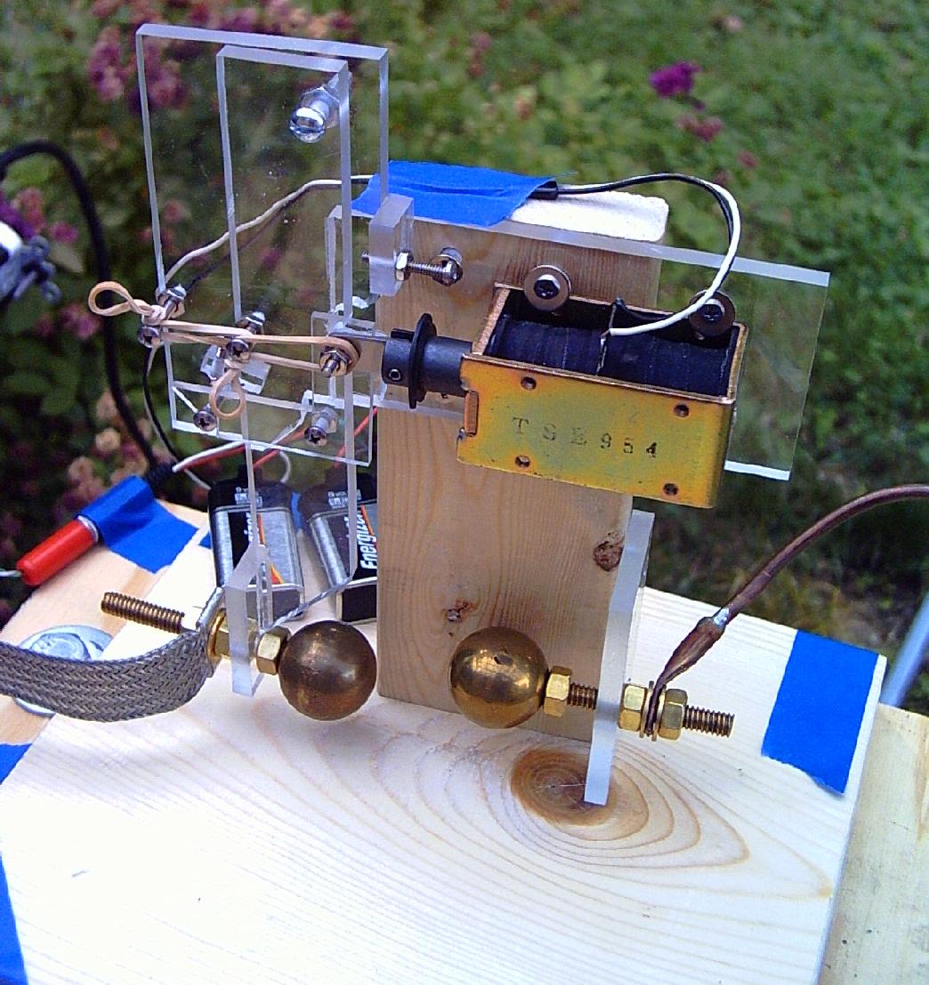
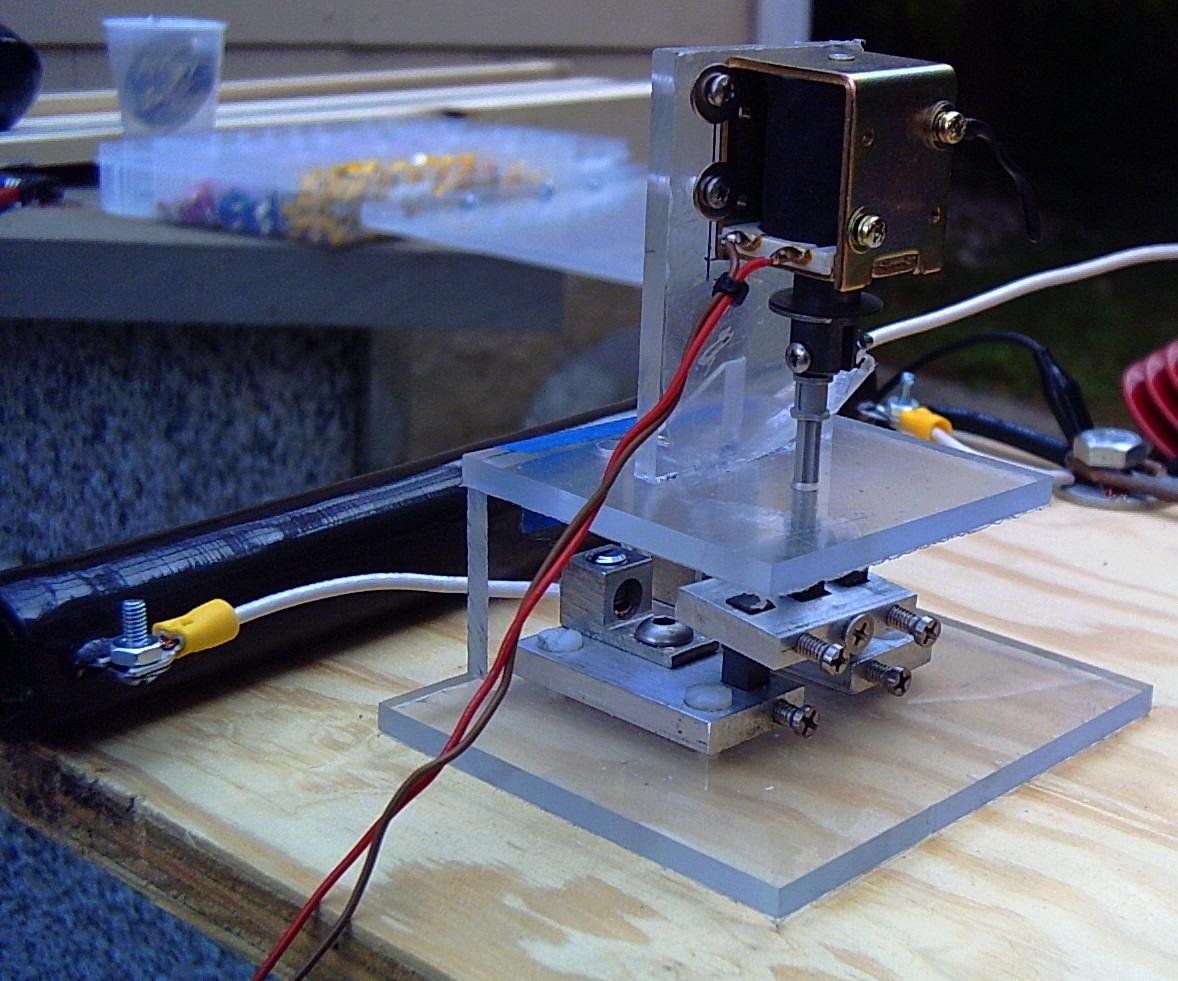
Finally, there is the spark gap. While its not inherently safety equipment, it is remotely operated, and the circuitry which activates it is isolated from the high power stuff.
The spark gap is another high voltage relay, only the contacts don't actually close, they just get very close. The electricity then jumps across. If the electrodes did touch, the arc would weld them together. The spark gap did get welded closed on one attempt. Luckily it was a relatively low voltage (500V), and I was able to pry it apart. (Those brass spheres were not cheap, and drilling and tapping the holes in them for the threaded rod they are mounted on was definitely annoying.)
I started out charging the capacitor to 200 volts, and then discharging it with the dump switch. When that seemed to work, I then charged the capacitor again, and discharged it with the spark gap through 6 inches of nichrome wire. (A nice non-inductive load, ringing is hard on the capacitor).
I then repeated that operation, increasing the voltage about 200 volts at a time.
Things were pretty boring until 500 volts. The dump switch would discharge in 10 seconds, and the spark gap produced an audible snap. The electrodes were also welded together at 500V, but came apart. I readjusted the gap, and continued.
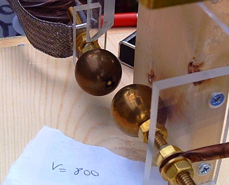
At 800V, the dump switch discharged in 12 seconds, and the spark gap, which had been snapping, started smoking too.
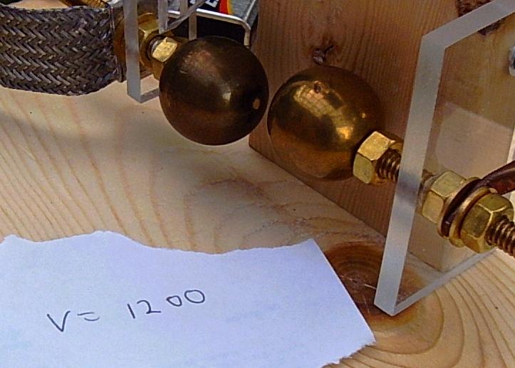
At 1200V, there was a visible flash in the dump switch. However it was not particularly reproducible.
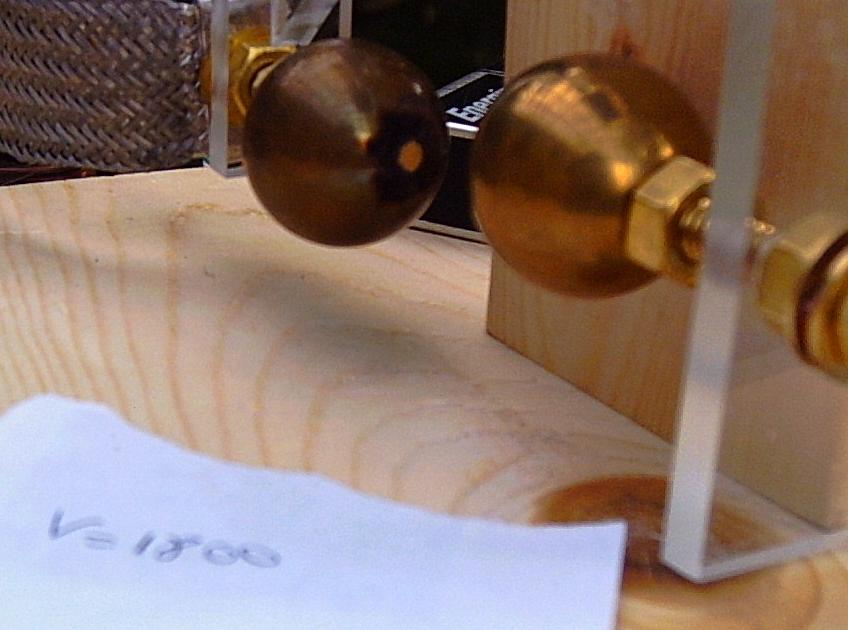
At 1800V, the dump switch discharged in 28 seconds, and the spark gap started getting loud. The nichrome wire also started getting discolored, with a layer of iridescent blue oxide with fingerprints in it.
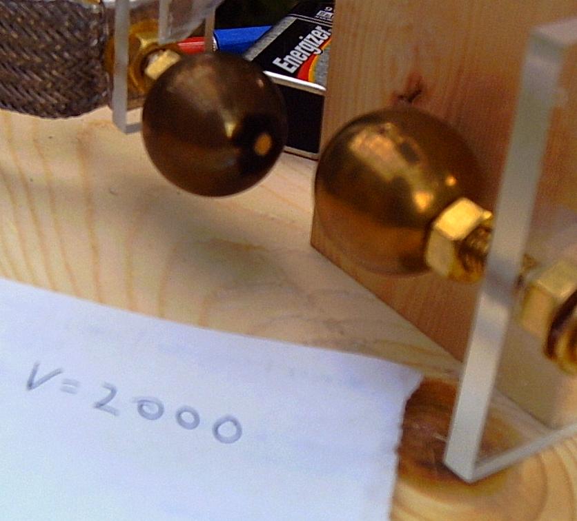
At 2000V, the nichrome wire flashed red-hot, then cooled off in about 2 seconds.
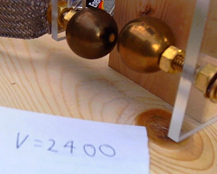
At 2400V, the nichrome wire vaporized, and scattered incandescent bits of metal over the apparatus. So much for the nice clean wood. Guess I should have painted it...
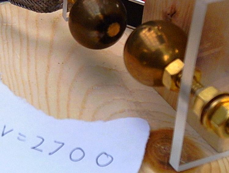
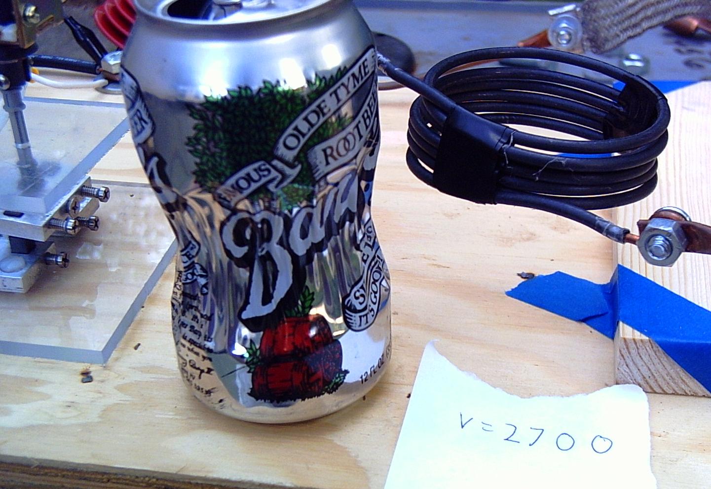
At 2700V, the limit of this charging power supply, the can was quite deformed and the spark gap was painfully loud. I put on my ear muffs... The neighbors (I did warn them about it... :-) did not comment.
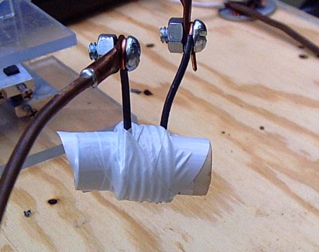
I also tried shrinking a dime. The dime is pinched between two pieces of dowel, which the coil is then wrapped around, and the whole mess wrapped in electrical tape. The coil was made from 6 turns of 14 gauge house wire. It arced between two of the turns, and while the dime was detectably deformed it was not impressive. I read about the dowel method on this web page.