 (click to enlarge)
This is my latest time-waster. These propellor clocks are becoming quite popular for some reason. You can buy one at the mall for like sixty bucks, or you can make your own hideous one for about sixty bucks. This one cost nothing because I had all the parts lying around or cannibalized some other devices to get them.
The clock is basically a board with a microcontroller and some LEDs; the board is whipped around by a motor and the LEDs blink. A phenomenon known as persistence of vision makes the "trail" that you can see in the photo. (Cameras also have persistence of vision, but for another reason.) Some people like to make their propellor display the time, stock quotes, or things like "all your base.."
The hard part about making this thing is getting electricity to a circuit board that's attached to a motor and spinning around in space. There are a couple of ways to accomplish this; you could use batteries mounted on the propellor or spin the propellor in a magnetic field. Some people have suggested mounting a second motor, to be used as a generator, on the spinning board. Once you require more than a few LEDs, though, the amount of current required becomes pretty large. None of these solutions are great for supplying more than a hundred milliamps or so.
You'd really like to use a slip ring, a device that mounts at the shaft so that one side is fixed and one is rotating with the propellor. Sliding contacts inside the slip ring carry current between the fixed and rotating halves. Slip rings can be made with large numbers of contacts if necessary, and they can be built to handle large currents. Unfortunately, nobody sells them because they're obnoxiously expensive. You pretty much have to make your own.
There is an alternative if you are content with supplying only power through the rotating joint. This is exactly what the commutator of a motor does; the power is delivered to the motor winding through its brushes. You can hack a motor apart, remove the windings, and use the commutator for the hub of your project.
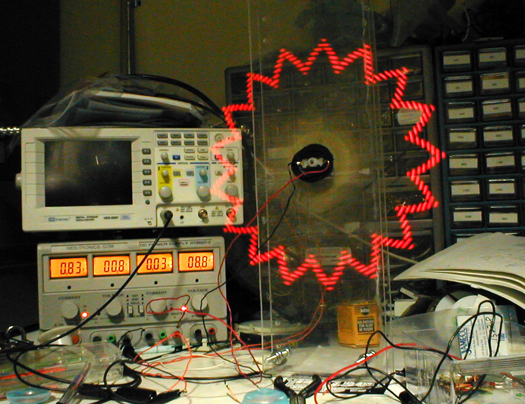
You can get info on hacking the motor here. This is a good web site so check out some other encoder articles while you're there. My commutator didn't come apart, so I was forced to provide power from the front of the device; you can see the back of the cannibalized motor in the photo. It is not held in place by electrical tape; the tape is to prevent the epoxy from leaking out while it set. The motor is in the back and is much too small for the job it's doing. You can see that it's drawing almost an amp from the power supply. The scanning assembly is also drawing a large amount of current, but that is reasonable; I used an old, worn-out motor that wastes a lot of power in its brushes. You will have better results with a brand-new motor.
You will have to carefully filter the power being supplied to your project through the ring. Even a good set of brushes will put a lot of noise into the power supply. I used a 7805 and a bunch of capacitors to power the PIC. You may also find that after you build it, you will have to spin the propellor for a few minutes to get it to work. Each time you remove and replace the commutuator, you will cause some minor damage to the brushes and they'll have to re-seat themselves.
This document, and all other documents, images, and other files contained within this site are copyrights of their respective owners. No file may be duplicated without explicit written permission of the author unless permission is otherwise noted here.