Dan Barlow's Webpage
Ray Tracing
Back to GraphicsI currently use POVRay for ray traced graphics. I have been using it since the mid 1990s to create images.
Raytracing is the opposite of traditional 3D graphics where triangles are rendered.
Instead, pixels in the image are traced back through a virtual camera into a landscape made of mathematical objects. This has the following benefits:
- No triangulation errors on smooth curves. Round things are round!
- Lighting, shadows, reflections, refractions, haze, particles, and luminous effects can be calculated accurately.
- Since the objects are mathematical, they can be described by formula instead of triangle meshes.
- Since the textures and colors are mathematical, they can be procedurally generated (not limited by saved texture maps).
- Since the camera is also a mathematical object, transformations can be applied to it directly for special effects.
It also has the following drawbacks:
- Raytracing is extremely computationally intensive. It is only recently possible to do ray tracing close enough to real time to provide it as an option on graphics cards.
- Specifying a scene mathematically using Constructive Solid Geometry requires a different mindset.
Here is an example: Render an image of a diamond.
Reference the steretype associated with "diamond shaped" - the Brilliant Cut.
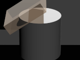
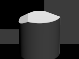
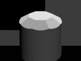
Choose a "base object" to modify which will minimize extra work. In this case a cylinder will work, and we designate the top of the cylinder as the "table" of the diamond. The cylinder will have a height of two and a radius of one.
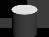 cylinder { <0,0,0>, <0,2,0>, 1 }
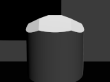
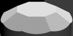
Decide on a geometry removal strategy. The first cut shall be at 34 degrees to the table and the series of cuts shall leave 54% of the radius present.
This cut can be thought of as a grinding stone held at a 34 degree angle, offset 0.54 of the radius, and ground down into the cylinder until the center of the block meets the top of the cylinder.
Then the stone is rotated 45 degrees on its stand and the cut is repeated.
 box { <-1, 0, -1>,< 1, 1, 1> rotate<0,0,34> translate<-.54,2,0> }
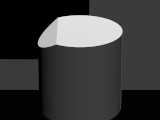
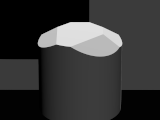
- Repeat the process of cutting and rotating according to the design specification.
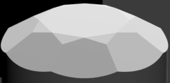
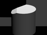
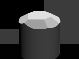
The final cuts list can be expressed as a series of loops:
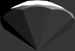
#declare Diamond_Diameter = 2.0; #declare Diamond = difference { // body cylinder { <0,0,0>, <0,2,0>, Diamond_Diameter/2 } //kite facets #for (kiteangle,45,360,45) box { <-5.00, 0.00, -5.00>,< 5.00, 1.00, 5.00> rotate<0,0,34> translate<-.54*Diamond_Diameter/2,2,0> rotate<0,kiteangle,0> } #end // star facets #for (starangle,22.5,360,45) box { <-5.00, 0.00, -5.00>,< 5.00, 1.00, 5.00> rotate<0,0,17> translate<-.4989*Diamond_Diameter/2,2,0> rotate<0,starangle,0> } #end // Upper Girdle Facets #for (girdleangle,11.25,360,22.5) box { <-5.00, 0.00, -5.00>,< 5.00, 1.00, 5.00> rotate<0,0,38.37> translate<-.589*Diamond_Diameter/2,2,0> rotate<0,girdleangle,0> } #end //Pavilion main facets #for (pavilionangle,45,360,45) box { <-5.00, -1.00, -5.00>,< 5.00, 0.00, 5.00> rotate<0,0,(-40.6)> translate<.963*Diamond_Diameter/2,-.05,0> rotate<0,pavilionangle,0> } #end //Lower Girdle Facets #for (girdleangle,11.25,360,22.5) box { <-5.00, -1.00, -5.00>,< 5.00, 0.00, 5.00> rotate<0,0,-(40.6+4.37)> translate<-1.2985*Diamond_Diameter/2,1.95,0> rotate<0,girdleangle,0> } #end //Girdle Trim Facets #for (girdleangle,11.25,360,22.5) box { <-5.00, -1.00, -5.00>,< 0.00, 2.00, 5.00> rotate<0,0,0> translate<-0.98*Diamond_Diameter/2,0,0> rotate<0,girdleangle,0> } #end } - Choose the apperance specification.
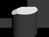
POVRay allows the specification of material properties at several levels of detail. The above examples were specified as
material{ texture { pigment {rgb 0.9} finish { ambient 0 diffuse 1 } } }
This breaks down as: The color shall be 90% grey. The object shall show only light that strikes it.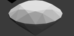
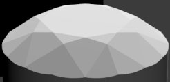
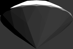
Here is an example of a basic diamond material. Diamond is colorless in transmission with a refractive index of 2.418. It has a high color dispersion of 0.044 which causes colorful sparkles.
This code adds specular reflections, and specifies that the material is transparent with an IOR of 2.418. As you can see, just having the Index of Refraction correct does not produce any sparkle. There is an addional setting for Dispersion.
material {
   texture  { pigment {rgbt 1} finish { ambient 0.0 diffuse 0.05 specular 0.6 roughness 0.005 reflection { 0.1, 1.0 fresnel on } conserve_energy } }
   interior { ior 2.418 fade_power 1001 fade_distance 0.9 fade_color <2,2,2>  }
}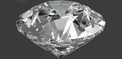
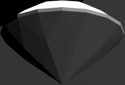
Now we add some color by specifying
interior { ior 2.418 dispersion 0.044 dispersion_samples 10 fade_power 1001 fade_distance 0.9 fade_color <1.04,1.04,1.04> }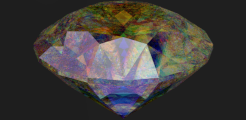
Finally, POVRay supports the tracing of photons through materials to support additional effects. This code specifies that the material will pass the photons through instead of collecting them.
photons { collect off target 0.5 refraction on reflection on }
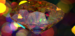 Fire!
Fire!
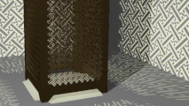
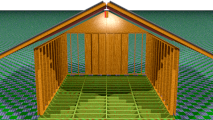
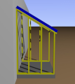
I use raytraced graphics as art, to visualize CAD and optics geometry, and as a sanity check on architectural designs.