Dan Barlow's Webpage
Arduino MEGA 2560 Memory Expansion 32K Shield > Available <
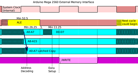
Back to ShieldsThe Arduino MEGA 2560 provides for an external memory bus. However, the lower 8 address bits are multiplexed with the 8 data bits to save pins.
The datasheet specifies that a fast latch be used to capture the address bits. The information is held for only FIVE nanoseconds after the latch is enabled. The 74AHC573 meets the requirement.
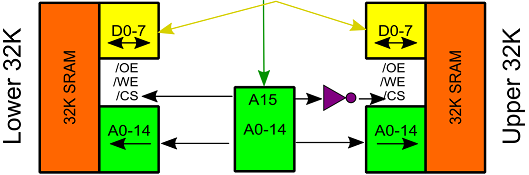
32K SRAMs are widely available whereas 64K are not. Two 32K SRAMs can be decoded with an inverter.
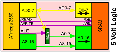
The demultiplexing requires that the eight lines AD0 to AD7 be wired to both the latch and the data port of the device. This creates some design complexity.
This shield implements a 32768 byte Static Random Access Memory mapped into the upper half of the address space, giving four times more available RAM.
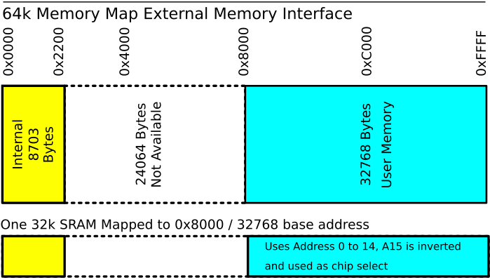
Arduino sketches can use the extra memory with minor additional code. Andy Brown wrote an external memory library which can be used with a minor change to xmem.h: #define XMEM_START ((void *)0x8000).
An example sketch is provided that shows how to use and test the memory.
The MEGA 2560 shield template was provided by G.Martino as part of the Arduino project.
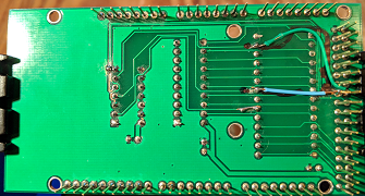
The first prototype has field corrections because I used an incorrect pinout chart that represented the read and write signals as active high. If that were true they would need to be inverted to work with the active low signals of the SRAM. On the prototype I used an inverter on those two lines. While reviewing the manufacturer's datasheet I realized that they were already active low, so the lines were moved to come directly from the header pins. The production version of the board has been corrected.
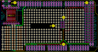
The prototype uses sockets to allow more flexibility in testing.
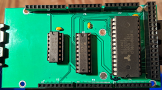
The production board is now available for purchase. U1 is a 74AHC04 inverter. U2 is a 74AHC573 transparent latch. U3 is a 32K by 8 bit Static RAM (AS6C62256 55ns or similar).
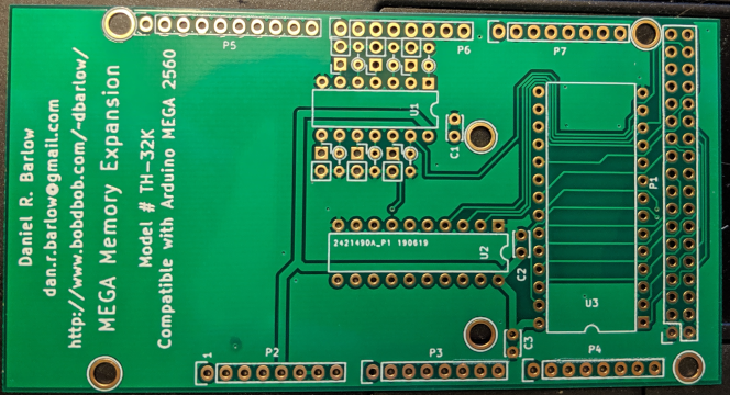
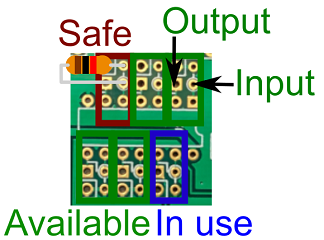
U1 has six inverters, of which only the one on pins 13,12 is used. The other five can be used for your projects.
If you are not using one, put a resistor from its input to ground to avoid RF interference. The exact value isn't important. 10K ohms is fine, and so is a jumper wire to ground.
Ground pads are provided on both sides for your wiring.
Input pins would be 1, 3, 5, 9, and 11. You can recognize them by the round pad. Outputs are square.